How to Send E-mail using PIC Microcontroller and ESP8266
ELECTRONICS
Sending Email using ESP8266 and PIC Microcontroller
In this tutorial let us learn how to send E-mails from PIC Microcontroller using famous WiFi module the ESP8266. This tutorial uses PIC16F877A IC and MPLABX and XC8 compiler for programming.
At the end of this tutorial you will be able to send E-mail from any normal E-mail ID like Gmail, yahoo etc to any other E-mail ID. Hence this tutorial assumes that you have some basic knowledge on ESP8266-01 Modules and PIC Microcontrollers. If not, the following tutorials will help you
So let us get started...
Getting ready with you E-mail ID:
Once you have decided from which mail ID you want to send the emails, follow the below steps
Step 1: Visit https://www.smtp2go.com/ and Sign up as a new user. Enter your name, E-mail address and password of your E-mail ID from which you want to send the mail.
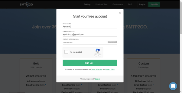
This tutorial uses the Mail ID: aswinthcd@ gmail.com and Password: circuitdigest.
Step 2: Click on sign up and you will be sent a verification mail to your entered mail ID. In this case it is aswinthcd@ gmail.com. Open the mail and click on “ACTIVATE ACCOUNT”
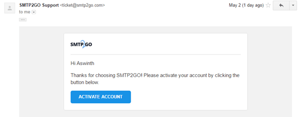
Step 3: It might ask for a password again, if asked enter the previous password. In this case it is 'circuitdigest'. Then you will be logged in to the SMPT2GO website. That is it now your E-mail address is ready to send mails using the ESP8266 Module.
Step 4: The last step is to encode the E-mail ID and password into base 64 format by using this website https://www.base64encode.org/. We are going to use this in our PIC program
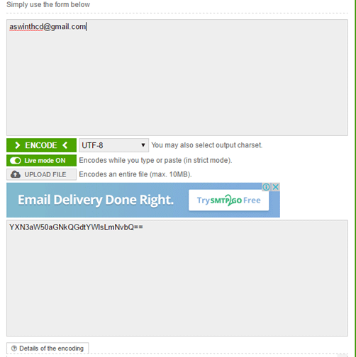
In this case the encoded values will look as shown in table below.
Parameter
|
Normal format
|
Encoded in base 64
|
Mail ID
|
aswinthcd@ gmail.com
|
YXN3aW50aGNkQGdtYWlsLmNvbQ==
|
Password
|
circuitdigest
|
Y2lyY3VpdGRpZ2VzdA==
|
Getting your Hardware Ready:
The complete schematic of the project is shown below.

The LCD display is used here for debugging purpose. It is not mandatory for you to connect this. The program will work fine even without the LCD display. If you want to know more about the schematics you visit this tutorial. (Interfacing PIC with ESP).
You can simply assemble this circuit on a breadboard and then proceed with the programming.
Programming your PIC to send E-mail:
In order to send an E-mail from the ESP8266 a sequence of AT commands has to be sent to the ESP module. The following steps have to be followed to send an E-mail from ESP8266.
- Set the module in AP+STA (Access Point and station) mode
- Connect to an Access point to get internet connection
- Enable multiple connections
- Start a server on any specific port
- Establish a TCP connection with SMPT2GO website
- Navigate to the Login section of the website
- Enter the E-mail ID and Password in base64 format
- Enter From mail ID
- Enter To mail ID
- Enter the Subject of the mail
- Enter the body of the mail
- Indicate the end of mail
- Send the mail
- Quit the TCP connection
It is a bit lengthy and tedious process but do not worry. I have simplified the process by creating a header file and you can use it directly by just calling some functions (explained below) which makes this task very easy. The complete code along with the header file can be downloaded from here.
Note: If you are using the code in a new project make sure you download the header file and add it in your project.
I have explained some important parts of the code below, the other parts are self explanatory. But if you have any doubts feel free to use the comment section.
/*Check if the ESP_PIC communication is successful*/

    do

    {

    Lcd_Set_Cursor(1,1);

    Lcd_Print_String("ESP not found");

    }while (!esp8266_isStarted()); //wait till the ESP send back "OK"

    Lcd_Set_Cursor(1,1);

    Lcd_Print_String("ESP is connected");

    __delay_ms(1500);

    Lcd_Clear();

    /*Yes ESP communication successful -Proceed*/
This part of the code is used to check if there is a proper communication established between the PIC and ESP8266. Only if, both of them could send and receive data through USART the program will proceed to next step.
esp8266_mode(3);
This function will set the ESP8266 in mode 3. Meaning the module can now act as a Access point and also as a server.
esp8266_connect("BPAS home","cracksun");
This function is used to connect your ESP8266 module to your Wifi Router. In this case “BPAS home” is the name of my Wifi signal and “cracksun” is my password. You have to use your own Wifi signal details.
_esp8266_enale_MUX(); //Enable multiple connections

_esp8266_create_server(); //Create a server on port 80
These two functions are used to enable multiple connections and create a server on port 80.
_esp8266_connect_SMPT2GO();
Now, using this function we can establish a TCP connection with SMPT2GO. Once the connection is establish this function also moves to the Login page of the website.
_esp8266_login_mail("YXN3aW50aGNkQGdtYWlsLmNvbQ==","Y2lyY3VpdGRpZ2VzdA==");
Use this function to enter your Email ID and password in base 64 format. As you can see these encoded values are same as that shown in the table above. Your encoded values will vary based on your E-mail ID and password.
_esp8266_mail_sendID("aswinthcd@ gmail.com");
This function is used to define the name of the sender ID. In this tutorial I am sending the mail using my Gmail ID aswinthcd@ gmail.com hence I have passed it as a parameter.
_esp8266_mail_recID("mailtoaswinth@ gmail.com");
This function is used to define the name of the receiver ID. I would like to send my mails to another Gmail account of mine, hence I have passed the parameter as mailtoasiwnth@ gmail.com. You can use your desired mail ID
_esp8266_start_mail();
This function instructs the SMPT2GO server that we are going to feed in the subject and body of the mail and makes it prepared for the same.
_esp8266_mail_subject("Mail from ESP8266");
You can use this function to define the subject of the mail. As an example I have used “Mail from ESP8266” as the subject of the mail.
_esp8266_mail_body("Testing Success -CircuitDigest");
After entering the subject you can enter the body of the mail using this function. As an example I have set “Testing Success –CircuitDigest” as the body of my mail.
_esp8266_End_mail();
Now that we have entered the subject and body of the mail we have to instruct the SMPT2GO server that we are done with adding details to the mail. This can be done by using the function
_esp8266_End_mail();
_esp8266_disconnect_SMPT2GO();
Finally after sending the mail, we have to terminate the TCP connection with the SMPT2GO server. This is done by using the above function.
Working:
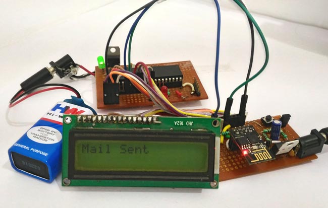
Once you are done with your hardware and program. Simply dump the code into you PIC MCU. Then power ON your circuit. If everything goes as expected, your LCD should display the status of the process and finally end up saying “Mail sent” as shown in the video below. Your hardware might look something like this.
Once the LCD shows that the mail is sent, check your Inbox and Spam folder for the sent mail. You should have received the mail as shown below..
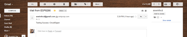
That is it now you can make your own IOT projects by reading a sensor data and sending them to your mail ID. Create a Security alert system for your home or automobiles by triggering an alert through mail.
If you have any doubt or go stuck in the middle kindly use the comment section and I will be happy to help you out.
[Note: make sure to replace the email address and password in the source code]
Code
#define _XTAL_FREQ 20000000
#define RS RD2
#define EN RD3
#define D4 RD4
#define D5 RD5
#define D6 RD6
#define D7 RD7
#define EN RD3
#define D4 RD4
#define D5 RD5
#define D6 RD6
#define D7 RD7
#include <xc.h>
#include "esp8266_functions.h"
#include "esp8266_functions.h"
#pragma config FOSC = HS // Oscillator Selection bits (HS oscillator)
#pragma config WDTE = OFF // Watchdog Timer Enable bit (WDT disabled)
#pragma config PWRTE = OFF // Power-up Timer Enable bit (PWRT enabled)
#pragma config BOREN = ON // Brown-out Reset Enable bit (BOR enabled)
#pragma config LVP = OFF // Low-Voltage (Single-Supply) In-Circuit Serial Programming Enable bit (RB3 is digital I/O, HV on MCLR must be used for programming)
#pragma config CPD = OFF // Data EEPROM Memory Code Protection bit (Data EEPROM code protection off)
#pragma config WRT = OFF // Flash Program Memory Write Enable bits (Write protection off; all program memory may be written to by EECON control)
#pragma config CP = OFF // Flash Program Memory Code Protection bit (Code protection off)
#pragma config WDTE = OFF // Watchdog Timer Enable bit (WDT disabled)
#pragma config PWRTE = OFF // Power-up Timer Enable bit (PWRT enabled)
#pragma config BOREN = ON // Brown-out Reset Enable bit (BOR enabled)
#pragma config LVP = OFF // Low-Voltage (Single-Supply) In-Circuit Serial Programming Enable bit (RB3 is digital I/O, HV on MCLR must be used for programming)
#pragma config CPD = OFF // Data EEPROM Memory Code Protection bit (Data EEPROM code protection off)
#pragma config WRT = OFF // Flash Program Memory Write Enable bits (Write protection off; all program memory may be written to by EECON control)
#pragma config CP = OFF // Flash Program Memory Code Protection bit (Code protection off)
//****LCD Functions Developed by Circuit Digest.***///
void Lcd_SetBit(char data_bit) //Based on the Hex value Set the Bits of the Data Lines
{
if(data_bit& 1)
D4 = 1;
else
D4 = 0;
void Lcd_SetBit(char data_bit) //Based on the Hex value Set the Bits of the Data Lines
{
if(data_bit& 1)
D4 = 1;
else
D4 = 0;
if(data_bit& 2)
D5 = 1;
else
D5 = 0;
D5 = 1;
else
D5 = 0;
if(data_bit& 4)
D6 = 1;
else
D6 = 0;
D6 = 1;
else
D6 = 0;
if(data_bit& 8)
D7 = 1;
else
D7 = 0;
}
D7 = 1;
else
D7 = 0;
}
void Lcd_Cmd(char a)
{
RS = 0;
Lcd_SetBit(a); //Incoming Hex value
EN = 1;
__delay_ms(4);
EN = 0;
}
{
RS = 0;
Lcd_SetBit(a); //Incoming Hex value
EN = 1;
__delay_ms(4);
EN = 0;
}
Lcd_Clear()
{
Lcd_Cmd(0); //Clear the LCD
Lcd_Cmd(1); //Move the curser to first position
}
{
Lcd_Cmd(0); //Clear the LCD
Lcd_Cmd(1); //Move the curser to first position
}
void Lcd_Set_Cursor(char a, char b)
{
char temp,z,y;
if(a== 1)
{
temp = 0x80 + b - 1; //80H is used to move the curser
z = temp>>4; //Lower 8-bits
y = temp & 0x0F; //Upper 8-bits
Lcd_Cmd(z); //Set Row
Lcd_Cmd(y); //Set Column
}
else if(a== 2)
{
temp = 0xC0 + b - 1;
z = temp>>4; //Lower 8-bits
y = temp & 0x0F; //Upper 8-bits
Lcd_Cmd(z); //Set Row
Lcd_Cmd(y); //Set Column
}
}
{
char temp,z,y;
if(a== 1)
{
temp = 0x80 + b - 1; //80H is used to move the curser
z = temp>>4; //Lower 8-bits
y = temp & 0x0F; //Upper 8-bits
Lcd_Cmd(z); //Set Row
Lcd_Cmd(y); //Set Column
}
else if(a== 2)
{
temp = 0xC0 + b - 1;
z = temp>>4; //Lower 8-bits
y = temp & 0x0F; //Upper 8-bits
Lcd_Cmd(z); //Set Row
Lcd_Cmd(y); //Set Column
}
}
void Lcd_Start()
{
Lcd_SetBit(0x00);
for(int i=1065244; i<=0; i--) NOP();
Lcd_Cmd(0x03);
__delay_ms(5);
Lcd_Cmd(0x03);
__delay_ms(11);
Lcd_Cmd(0x03);
Lcd_Cmd(0x02); //02H is used for Return home -> Clears the RAM and initializes the LCD
Lcd_Cmd(0x02); //02H is used for Return home -> Clears the RAM and initializes the LCD
Lcd_Cmd(0x08); //Select Row 1
Lcd_Cmd(0x00); //Clear Row 1 Display
Lcd_Cmd(0x0C); //Select Row 2
Lcd_Cmd(0x00); //Clear Row 2 Display
Lcd_Cmd(0x06);
}
{
Lcd_SetBit(0x00);
for(int i=1065244; i<=0; i--) NOP();
Lcd_Cmd(0x03);
__delay_ms(5);
Lcd_Cmd(0x03);
__delay_ms(11);
Lcd_Cmd(0x03);
Lcd_Cmd(0x02); //02H is used for Return home -> Clears the RAM and initializes the LCD
Lcd_Cmd(0x02); //02H is used for Return home -> Clears the RAM and initializes the LCD
Lcd_Cmd(0x08); //Select Row 1
Lcd_Cmd(0x00); //Clear Row 1 Display
Lcd_Cmd(0x0C); //Select Row 2
Lcd_Cmd(0x00); //Clear Row 2 Display
Lcd_Cmd(0x06);
}
void Lcd_Print_Char(char data) //Send 8-bits through 4-bit mode
{
char Lower_Nibble,Upper_Nibble;
Lower_Nibble = data&0x0F;
Upper_Nibble = data&0xF0;
RS = 1; // => RS = 1
Lcd_SetBit(Upper_Nibble>>4); //Send upper half by shifting by 4
EN = 1;
for(int i=2130483; i<=0; i--) NOP();
EN = 0;
Lcd_SetBit(Lower_Nibble); //Send Lower half
EN = 1;
for(int i=2130483; i<=0; i--) NOP();
EN = 0;
}
{
char Lower_Nibble,Upper_Nibble;
Lower_Nibble = data&0x0F;
Upper_Nibble = data&0xF0;
RS = 1; // => RS = 1
Lcd_SetBit(Upper_Nibble>>4); //Send upper half by shifting by 4
EN = 1;
for(int i=2130483; i<=0; i--) NOP();
EN = 0;
Lcd_SetBit(Lower_Nibble); //Send Lower half
EN = 1;
for(int i=2130483; i<=0; i--) NOP();
EN = 0;
}
void Lcd_Print_String(char *a)
{
int i;
for(i=0;a[i]!='\0';i++)
Lcd_Print_Char(a[i]); //Split the string using pointers and call the Char function
}
//***End of LCD functions***//
{
int i;
for(i=0;a[i]!='\0';i++)
Lcd_Print_Char(a[i]); //Split the string using pointers and call the Char function
}
//***End of LCD functions***//
void main()
{
TRISD = 0x00;
Lcd_Start();
Initialize_ESP8266() ;
Lcd_Set_Cursor(1,1);
Lcd_Print_String("Circuit Digest");
Lcd_Set_Cursor(2,1);
Lcd_Print_String("Mail using ESP");
__delay_ms(1500);
Lcd_Clear();
/*Check if the ESP_PIC communication is successful*/
do
{
Lcd_Set_Cursor(1,1);
Lcd_Print_String("ESP not found");
}while (!esp8266_isStarted()); //wait till the ESP send back "OK"
Lcd_Set_Cursor(1,1);
Lcd_Print_String("ESP is connected");
__delay_ms(1500);
Lcd_Clear();
/*Yes ESP communication successful -Proceed*/
/*Put the module in AP+STA*/
esp8266_mode(3);
Lcd_Set_Cursor(1,1);
Lcd_Print_String("ESP set AP+STA");
__delay_ms(1500);
Lcd_Clear();
/*Module set as AP+STA*/
/*Connect to a AccesPoint*/
esp8266_connect("BPAS home","cracksun"); //Enter you WiFi name and password here, here BPAS home is the name and cracksun is the pas
Lcd_Set_Cursor(1,1);
Lcd_Print_String("Connected 2 WIFI"); //Print on LCD for debugging.
__delay_ms(1500);
Lcd_Clear();
/*Connected to WiFi*/
_esp8266_enale_MUX(); //Enable multiple connections
_esp8266_create_server(); //Create a server on port 80
_esp8266_connect_SMPT2GO(); //Establish TCP connection with SMPT2GO
/*LOG IN with your SMPT2GO approved mail ID*/
/*Visit the page https://www.smtp2go.com/ and sign up using any Gmail ID
* Once you gmail ID is SMPT2GO approved convert your mail ID and password in 64 base format
* visit https://www.base64encode.org/ for converting 64 base format online
* FORMAT -> _esp8266_login_mail("mailID in base 64","Password in base 64");
* This program uses the ID-> aswinthcd@ gmail.com and password -> circuitdigest as an example
*/
_esp8266_login_mail("YXN3aW50aGNkQGdtYWlsLmNvbQ==","Y2lyY3VpdGRpZ2VzdA==");
Lcd_Set_Cursor(1,1);
Lcd_Print_String("Login Successful"); //display on LCD for debugging
__delay_ms(1500);
Lcd_Clear();
/*End of Login*/
_esp8266_mail_sendID("aswinthcd@ gmail.com"); //The sender mail ID
_esp8266_mail_recID("mailtoaswinth@ gmail.com"); //The Receiver mail ID
_esp8266_start_mail();
_esp8266_mail_subject("Mail from ESP8266"); //Enter the subject of your mail
_esp8266_mail_body("Testing Success -CircuitDigest"); //Enter the body of your mail
_esp8266_End_mail();
_esp8266_disconnect_SMPT2GO();
Lcd_Set_Cursor(1,1);
Lcd_Print_String("Mail Sent"); //Print on LCD for debugging
while(1)
{
//do nothing
}
{
TRISD = 0x00;
Lcd_Start();
Initialize_ESP8266() ;
Lcd_Set_Cursor(1,1);
Lcd_Print_String("Circuit Digest");
Lcd_Set_Cursor(2,1);
Lcd_Print_String("Mail using ESP");
__delay_ms(1500);
Lcd_Clear();
/*Check if the ESP_PIC communication is successful*/
do
{
Lcd_Set_Cursor(1,1);
Lcd_Print_String("ESP not found");
}while (!esp8266_isStarted()); //wait till the ESP send back "OK"
Lcd_Set_Cursor(1,1);
Lcd_Print_String("ESP is connected");
__delay_ms(1500);
Lcd_Clear();
/*Yes ESP communication successful -Proceed*/
/*Put the module in AP+STA*/
esp8266_mode(3);
Lcd_Set_Cursor(1,1);
Lcd_Print_String("ESP set AP+STA");
__delay_ms(1500);
Lcd_Clear();
/*Module set as AP+STA*/
/*Connect to a AccesPoint*/
esp8266_connect("BPAS home","cracksun"); //Enter you WiFi name and password here, here BPAS home is the name and cracksun is the pas
Lcd_Set_Cursor(1,1);
Lcd_Print_String("Connected 2 WIFI"); //Print on LCD for debugging.
__delay_ms(1500);
Lcd_Clear();
/*Connected to WiFi*/
_esp8266_enale_MUX(); //Enable multiple connections
_esp8266_create_server(); //Create a server on port 80
_esp8266_connect_SMPT2GO(); //Establish TCP connection with SMPT2GO
/*LOG IN with your SMPT2GO approved mail ID*/
/*Visit the page https://www.smtp2go.com/ and sign up using any Gmail ID
* Once you gmail ID is SMPT2GO approved convert your mail ID and password in 64 base format
* visit https://www.base64encode.org/ for converting 64 base format online
* FORMAT -> _esp8266_login_mail("mailID in base 64","Password in base 64");
* This program uses the ID-> aswinthcd@ gmail.com and password -> circuitdigest as an example
*/
_esp8266_login_mail("YXN3aW50aGNkQGdtYWlsLmNvbQ==","Y2lyY3VpdGRpZ2VzdA==");
Lcd_Set_Cursor(1,1);
Lcd_Print_String("Login Successful"); //display on LCD for debugging
__delay_ms(1500);
Lcd_Clear();
/*End of Login*/
_esp8266_mail_sendID("aswinthcd@ gmail.com"); //The sender mail ID
_esp8266_mail_recID("mailtoaswinth@ gmail.com"); //The Receiver mail ID
_esp8266_start_mail();
_esp8266_mail_subject("Mail from ESP8266"); //Enter the subject of your mail
_esp8266_mail_body("Testing Success -CircuitDigest"); //Enter the body of your mail
_esp8266_End_mail();
_esp8266_disconnect_SMPT2GO();
Lcd_Set_Cursor(1,1);
Lcd_Print_String("Mail Sent"); //Print on LCD for debugging
while(1)
{
//do nothing
}
}