วันจันทร์ที่ 11 กุมภาพันธ์ พ.ศ. 2562

โครงงานที่14วงจรเครื่องนับจำนวณ

        โครงงานที่14วงจรเครื่องนับจำนวณ


code

int conv7segment(int number);
main()
{
 int i;
  TRISB = 0x00;
  CMCON = 0x07;
  TRISA = 0xFF;
  i = 0;
  while(1)
  {
    while(PORTA.F0==0)
    {
     i++;
     if(i>9)
     {
        i = 0;
     }
     while(PORTA.F0==0)
     {
       Delay_ms(10);
     }
    }
    while(PORTA.F1==0)
    {
     i--;
    if(i<0)
    {
       i = 9;
    }
    while(PORTA.F1==0)
    {
      Delay_ms(10);
    }
   }
   PORTB = conv7segment(i);
 }
}
int conv7segment(int number)
{
  switch(number)
  {
     case 1: return 0x06;
     case 2: return 0x5b;
     case 3: return 0x4f;
     case 4: return 0x66;
     case 5: return 0x6d;
     case 6: return 0x7d;
     case 7: return 0x07;
     case 8: return 0x7f;
     case 9: return 0x6f;
     case 0: return 0x3f;
  }
}

วันศุกร์ที่ 8 กุมภาพันธ์ พ.ศ. 2562

ไมโครคอนโทลเลอร์ 20

IR Remote Controlled Home Automation using PIC Microcontroller

ELECTRONICS
BySaddam 29
IR Remote Controlled Home Automation using PIC MicrocontrollerIR Remote Controlled Home Automation using PIC Microcontroller
In this project, we are going to use a PIC microcontroller to remotely control few AC loads by just using an IR remote. A similar project IR remote controlled Home automation has already been done with Arduino also, but here we designed it on PCB using EasyEDA’s online PCB designer and simulator, and used their PCB designing services to order the PCB boards as shown in the subsequent section of the article. 
At the end of this project you will be able to toggle (ON/OFF) any AC load using an ordinary Remote from the comfort of your Chair/Bed. To make this project more interesting we have also enabled a feature to control the speed of the fan with the help of Triac. All these can be done with simple clicks on your IR remote. You can use any of your TV/DVD/MP3 remote for this project. The different IR signals from the remote are received by the microcontroller which then controls the respective relays via a relay driver circuit. These relays are used to connect and disconnect the AC Loads (Lights/Fan).

Working Explanation:

The working of this project is fairly simple to understand. When a button is pressed on the IR Remote it sends a sequence of code in form of encoded pulses using 38Khz modulating frequency. These pulses are received by the TSOP1738 sensor and then read by the Controller. The Controller then decodes the received train of the pulses into a hex value and compares it with the predefined hex values in our program.
If any match occurs then the controller performs a relative operation by triggering the respective Relay/Triac and the corresponding result is also indicated by on-board LEDs. Here in this project, we have used 4 bulbs (small bulbs) of different colors as lighting loads and another bulb (bigger bulb) is considered to be a fan for demonstration purpose.
We have selected key 1 to toggle the relay1, 2 to toggle the relay2, 3 to toggle the relay3, 4 to toggle the relay4, and Vol+ to increase fan speed and Vol- to decrease speed of the fan.
Note: Here we have used 100watt bulb instead of a fan.

There are many types of IR Remotes available for different devices, but most of them work around 38KHz Frequency. Here in this project, we control home appliances using IR TV remote and for detecting the IR signals, we use a TSOP1738 IR Receiver. This TSOP1738 sensor can sense 38Khz Frequency signal. The working of IR remote and the TSOP1738 is covered in detail in this article: IR Transmitter and Receiver
Our PIC microcontroller operates at +5V and the Relays operate at +12V, Hence we use a transformer to step down the 220V AC and rectify it using a full bridge rectifier. This rectified DC voltage is then regulated to +12V and +5V by using the regulator ICs 7812 and 7805 respectively.
To trigger the relay we make use of transistors like BC547 which can act as an electronic switch to turn ON/OFF the relays based on the signal from the PIC microcontroller.Further to control the speed of the fan we are using a TRIAC. TRIAC is a power semiconductor which is capable of controlling the output voltage; this capability is used to control the speed of the fan.
We have also used a Triac Driver to control the Triac using our PIC microcontroller. This driver is used to give a firing angle pulse to Triac, so that the output power can be controlled. Here we have used 6 level of speed control. When the level is 0 then the fan will be off. When level will be 1 then speed will be 1/5th of full speed. When level will be 2 then speed will be 2/5th of full speed and respectively for others. The current level of the speed can be monitored using the on-board 7-segment display.

The block diagram of the project is shown below.
Working Block Diagram of IR Remote Controlled Home Automation using PIC

Components: 

The components required to build this project is given below:
  • PIC18f2520 Microcontroller           -1
  • TSOP1738                                       -1
  • IR TV/DVD Remote                      -1
  • Transistor BC547                            -4
  • Relays 12 volt                                 -4
  • Bulb with holder                             -5
  • Connecting wires                            -
  • EasyEda PCB                                 -1                    
  • 16x2 LCD
  • Power supply 12v
  • Terminal connector 2 pin     `           -8
  • Terminal Connector 3 pin                -1
  • Transformer 12-0-12                       -1                                             -
  • Voltage Regulator 7805                  -1
  • Voltage Regulator 7812                  -1
  • Capacitor 1000uf                            -1
  • Capacitor     10uf                             -1
  • Capacitor     0.1uf                            -1
  • Capacitor 0.01uf 400V       `           -1
  • 10k                                                  -5
  • 1k                                                    -5
  • 100ohm                                           -7
  • Common cathode segment -1
  • 1n4007 diode                                  -10
  • BT136 triac                                     -1
  • Male/female header             -
  • LEDs                                               -6
  • Opto-coupler moc3021                   -1
  • Opto-coupler mtc2e or 4n35           -1
  • 20Mhz crystal                                  -1
  • 33pf capacitor                                 -2
  • 5.1v zener diode                              -1
  • 47 ohm 2 watt resistor                     -1
All these components are commonly used and can be easily purchased. However if you are looking for a best buy online then we would recommend you LCSC.
LCSC is a great online store to buy your electronics components for all kinds of projects. They feature about 25,000 kinds of components and the best thing is that they sell even small quantity items for small projects and they also have Global Shipping.

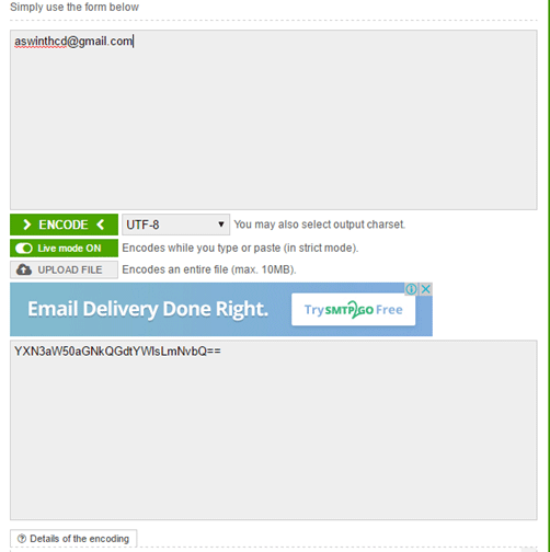
Decoding the IR Remote:
As said earlier you can use any kind remote for your project. But we have to know what kind of signal is generated for from that particular remote. For every individual key on the remote there will be an equivalent HEX value for that key. Using this HEX value we can distinguish between each key on our microcontroller side. So before we decide to use a remote we should know the HEX value for the keys preset in that particular remote. In this project, we have used a NEC remote. The HEX values for the keys on a NEC remote is given below.
decimal hex key
As you can notice the HEX value has 7 characters out of which only the last two differs, hence we can consider only the last two digits to distinguish between each keys. 
key1
Circuit Diagram:
The schematic for the project is shown below.
 Circuit Diagram for PIC Microcontroller Based Remote Controlled Home Automation
The above schematic was made easy by using esayEDA schematic editor since they provide the layouts of all components used in this project. It also does not require an installation and can be used online on the go. 
The pinouts and component values are clearly specified in the schematic above. You can also download the schematic file from here.

Programming:

The program for this project is done using MPLABX, the code is also pretty simple and easy to understand. The complete code will be given at the end of this tutorial, further few important chunks of the program are explained below.
In the beginning of the code, we should include required libraries, define the pins and declare the variables.
#include <xc.h>
#include<string.h>
#include<stdlib.h>
#include "config.h"

#define tric RB1
#define ir RB2

#define relay1 RC2
#define relay2 RC3
#define relay3 RC4
#define relay4 RC5

#define rly1LED RB3
#define rly2LED RB4
#define rly3LED RB5
#define rly4LED RC1
#define fanLED RC0

int flag=0;
int cmd=0;
int speed=5;
unsigned int dat[100];
int i=0;
char result[10];
int j=0;
After that, we have created a simple delay function by using the “for” loop.
void delay(int time)
{
    for(int i=0;i<time;i++)
        for(int j=0;j<800;j++);
}
After that, we have initialized the timer by using the following function
void timer()           // 10 -> 1us
{
   T0PS0=0;
   T0PS1=0;
   T0PS2=0;
   PSA=0;      //Timer Clock Source is from Prescaler
   T0CS=0;     //Prescaler gets clock from FCPU (5MHz)
   T08BIT=0;   //16 BIT MODE
   TMR0IE=1;   //Enable TIMER0 Interrupt
   PEIE=1;     //Enable Peripheral Interrupt
   GIE=1;      //Enable INTs globally
   TMR0ON=1;      //Now start the timer!
}
Now in the main function, we have give directions to the selected pins and initialize timer and external interrupt int0 to detect zero crossing.
   ADCON1=0b00001111;
   TRISB1=0;
   TRISB2=1;
   TRISB3=0;
   TRISB4=0;
   TRISB5=0;
   TRISC=0x00;
   TRISA=0x00;
   PORTA=0xc0;            
   TRISB6=0;
   RB6=1;
    relay1=0;
    relay2=0;
    relay3=0;
    relay4=0;
    rly1LED=0;
    rly3LED=0;
    rly2LED=0;
    rly4LED=0;
    fanLED=0;
        i=0;
    ir=0;
    tric=0;
    timer();
    INTEDG0 = 0; // Interrupt on falling edge
    INT0IE = 1; // Enable the INT0 external interrupt (RB0)
    INT0IF = 0; // Clears INT0 External Interrupt Flag bit
    PEIE=1;     //Enable Peripheral Interrupt
    GIE=1;      //Enable INTs globally
Now, here we are not using any interrupt or capture and compare mode to detect IR signal. Here we have just used a digital pin to read data just like we read a push button. Whenever signal goes high or low we just put debouncing method and run the timer. Whenever pin changes its state to another then time values will be saved in an array.
IR remote send logic 0 as 562.5us and logic 1 as 2250us. Whenever timer reads around 562.5us then we assume it 0 and when timer reads around 2250us then we assume it as 1. Then we convert it in hex.
The incoming signal from remote contains 34 bits. We store all the bytes in the array and then decode the last byte to use.
      while(ir == 1);
       INT0IE = 0;
       while(ir == 0);
       TMR0=0;
       while(ir == 1);
       i++;
       dat[i]=TMR0;

       if(dat[1] > 5000 && dat[1]<12000)
       {
       }
       else
       {
           i=0;
           INT0IE = 1;
       }

       if(i>=33)
       {
        GIE=0;
        delay(50);
        cmd=0;
        for(j=26;j<34;j++)
        {
            if(dat[j]>1000 && dat[j]<2000)
                cmd<<=1;

            else if(dat[j]>3500 && dat[j]<4500)
            {
                cmd|=0x01;
                cmd<<=1;
            }
        }
        cmd>>=1;
The above piece of code receives and decodes the IR signal using timer interrupts and stores the corresponding HEX value in the variable cmd. Now we can compare this HEX value (cmd variable) with our predefined HEX values and toggle the relay as shown below
if(cmd == 0xAF)
         {
             relay1=~relay1;
             rly1LED=~rly1LED;
         }

         else if(cmd == 0x27)
         {
             relay2=~relay2;
             rly2LED=~rly2LED;
         }
        
         else if(cmd == 0x07)
         {
             relay3=~relay3;
             rly3LED=~rly3LED;
         }
         else if(cmd == 0xCF)
         {
             relay4=~relay4;
             rly4LED=~rly4LED;
         }
         else if(cmd == 0x5f)
         {
             speed++;
             if(speed>5)
             {
                 speed=5;
             }
         }

         else if(cmd == 0x9f)
         {
             speed--;
             if(speed<=0)
             {
                 speed=0;
             }
         }
Now to know at which our fan is currently operating, we should use a 7-segment display. The following lines are used to instruct the pins of the 7-segment display.
if(speed == 5)        // turned off  5x2= 10ms triger    //speed 0
        {
            PORTA=0xC0;           // display 0
            RB6=1;
            fanLED=0;            
        }      

        else if(speed == 4 )    //  8 ms trigger    //speed 1
        {
            PORTA=0xfc;        // displaying 1
            RB6=1;
            fanLED=1;
        }
       
        else if(speed == 3)   //   6 ms trigger       // speed 2
        {
            PORTA=0xE4;       // displaying 2                   
            RB6=0;
            fanLED=1;
        }
       
        else if(speed == 2)   // 4ms trigger  // speed 3
        {
            PORTA=0xF0;       // displaying 3
            RB6=0;
            fanLED=1;
        }
       
        else if(speed == 1)    // 2ms trigger  // speed 4
        {
            PORTA=0xD9;          // displaying 4
            RB6=0;
            fanLED=1;
        }
    
        else if(speed == 0)        // 0ms trigger  // speed 5  full power
        {
           PORTA=0xD2;            // displaying 5
           RB6=0;
           fanLED=1;
        }
The below function is for external interrupt and time overflow. This function is responsible for detecting zero crossing and driving the Triac.
void interrupt isr()
{
    if(INT0IF)
    {
        delay(speed);
        tric=1;
        for(int t=0;t<100;t++);
        tric=0;
        INT0IF=0;
    }
  
   if(TMR0IF)  //Check if it is TMR0 Overflow ISR  
   {
      TMR0IF=0;
   }
}
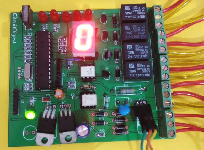
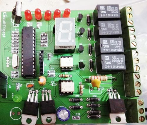
The final PCB for this IR remote controlled home automation looks as shown below:
Final PCB for PIC based remote controlled home automation project


Circuit and PCB Design using EasyEDA:

To design this  Remote control home automation we have used EasyEDA which is a free online EDA tool for creating circuits and PCBs in a seamless manner. We have previously ordered few PCBs from EasyEDA and still using their services as we found the whole process, from drawing the circuits to ordering the PCBs, more convenient and efficient in comparison of other PCB fabricators. EasyEDA offers circuit drawing, simulation, PCB design for free and also offers high quality but low price Customized PCB service. Check here for the complete tutorial on How to use Easy EDA for making Schematics, PCB layouts, Simulating the Circuits etc.
EasyEDA is improving day by day; they have added many new features and improved the overall user experience, which makes EasyEDA easier and usable for designing circuits. They are soon going to launch its Desktop version, which can be downloaded and installed on your computer for offline use.
In EasyEDA, you can make your circuit and PCB designs public so that other users can copy or edit them and can take benefit from there, we have also made our whole Circuit and PCB layouts public for this Remote control Home automation.
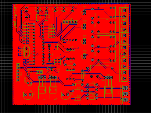
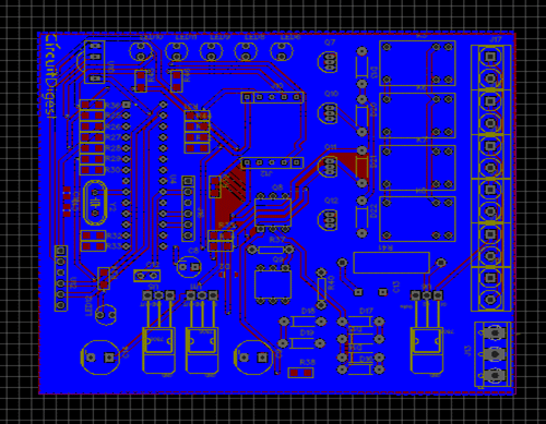
Below is the Snapshot of Top layer of PCB layout from EasyEDA, you can view any Layer (Top, Bottom, Topsilk, bottomsilk etc) of the PCB by selecting the layer form the ‘Layers’ Window. 
PCB Design for PIC based IR Remote Controlled Home Automation
IR Remote Home Automation PCB Design


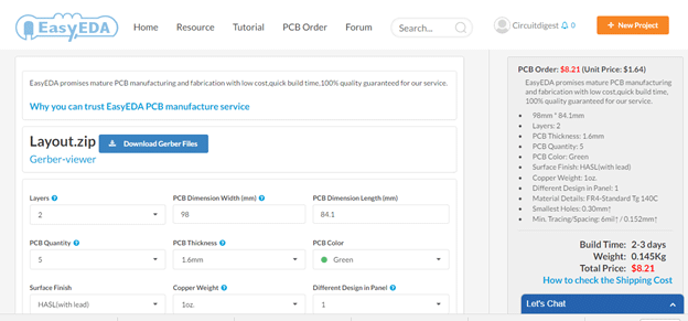
Calculating and Ordering PCB Samples online:

After completing the design of PCB, you can click the icon of Fabrication output, which will take you on the PCB order page. Here you can view your PCB in Gerber Viewer or download Gerber files of your PCB and send them to any manufacturer, it’s also a lot easier (and cheaper) to order it directly in EasyEDA. Here you can select the number of PCBs you want to order, how many copper layers you need, the PCB thickness, copper weight, and even the PCB color. After you have selected all of the options, click “Save to Cart” and complete your order, then you will receive your PCBs within few days.
Ordering PCB on EasyEDA
You can directly order this PCB or download the Gerber file using this link.
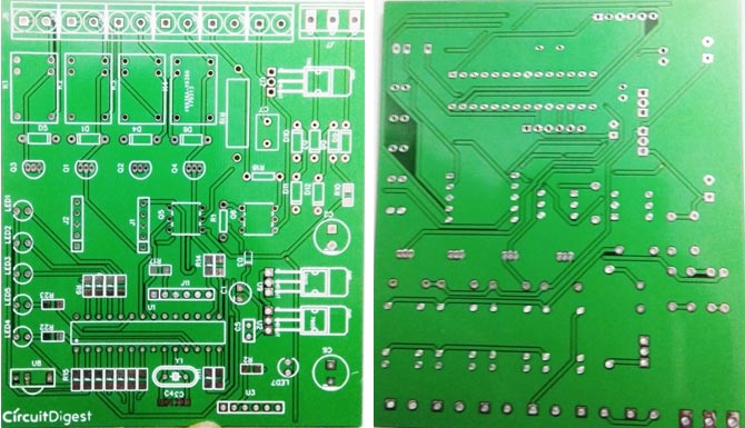
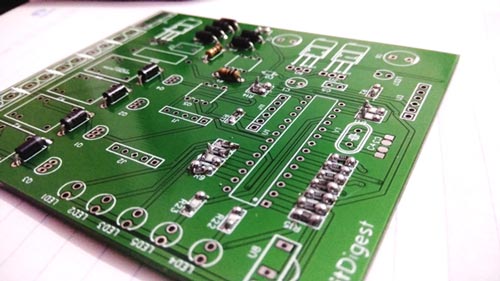
After few days of ordering PCB’s we got the PCBs. The boards that we received are shown below.
PCB boards for IR remote controlled home automation project
Once we received the PCBs I mounted all the required components over the PCB, and finally we have our IR Remote Controlled Home Automation ready, check this circuit working in demonstration video at the end of the article.
PIC home automation PCB after soldering components
PIC based home automation PCb
Code

#include <xc.h>
#include<string.h>
#include<stdlib.h>
#include "config.h"
#define tric RB1
#define ir RB2
#define relay1 RC2
#define relay2 RC3
#define relay3 RC4
#define relay4 RC5
#define rly1LED RB3
#define rly2LED RB4
#define rly3LED RB5
#define rly4LED RC1
#define fanLED RC0
int flag=0;
int cmd=0;
int speed=5;
unsigned int dat[100];
int i=0;
char result[10];
int j=0;
   
void delay(int time)
{
    for(int i=0;i<time;i++)
        for(int j=0;j<800;j++);
}
void timer()           // 10 -> 1us
{
   T0PS0=0; 
   T0PS1=0;
   T0PS2=0;
   PSA=0;      //Timer Clock Source is from Prescaler
   T0CS=0;     //Prescaler gets clock from FCPU (5MHz)
   T08BIT=0;   //16 BIT MODE
   TMR0IE=1;   //Enable TIMER0 Interrupt
   PEIE=1;     //Enable Peripheral Interrupt
   GIE=1;      //Enable INTs globally
   TMR0ON=1;      //Now start the timer!
}
void main(void) 
{
   ADCON1=0b00001111;
   TRISB1=0;
   TRISB2=1;
   TRISB3=0;
   TRISB4=0;
   TRISB5=0;
   TRISC=0x00;
   TRISA=0x00;
   PORTA=0xc0;             
   TRISB6=0;
   RB6=1;
    relay1=0;
    relay2=0;
    relay3=0;
    relay4=0;
    rly1LED=0;
    rly3LED=0;
    rly2LED=0;
    rly4LED=0;
    fanLED=0;
        i=0;
    ir=0;
    tric=0;
    timer();
    INTEDG0 = 0; // Interrupt on falling edge
    INT0IE = 1; // Enable the INT0 external interrupt (RB0) 
    INT0IF = 0; // Clears INT0 External Interrupt Flag bit
    PEIE=1;     //Enable Peripheral Interrupt
    GIE=1;      //Enable INTs globally
   while(1)
   {   
       while(ir == 1);
       INT0IE = 0;
       while(ir == 0);
       TMR0=0;
       while(ir == 1);
       i++;
       dat[i]=TMR0;
       
       if(dat[1] > 5000 && dat[1]<12000)
       {
       }
       else
       {
           i=0;
           INT0IE = 1;
       }
       if(i>=33)
       {
        GIE=0;
        delay(50);
        cmd=0;
        for(j=26;j<34;j++)
        {
            if(dat[j]>1000 && dat[j]<2000)
                cmd<<=1;
            else if(dat[j]>3500 && dat[j]<4500)
            {
                cmd|=0x01;
                cmd<<=1;
            }
        }
        cmd>>=1;
         
         if(cmd == 0xAF)
         {
             relay1=~relay1;
             rly1LED=~rly1LED;
         }
         
         else if(cmd == 0x27)
         {
             relay2=~relay2;
             rly2LED=~rly2LED;
         }
         
         else if(cmd == 0x07)
         {
             relay3=~relay3;
             rly3LED=~rly3LED;
         }
         
         else if(cmd == 0xCF)
         {
             relay4=~relay4;
             rly4LED=~rly4LED;
         }
         
         else if(cmd == 0x5f)
         {
             speed++;
             if(speed>5)
             {
                 speed=5; 
             }
         }
         
         else if(cmd == 0x9f)
         {
             speed--;
             if(speed<=0)
             {
                 speed=0; 
             }
         }
         
        if(speed == 5)        // turned off  5x2= 10ms triger    //speed 0
        {
            PORTA=0xC0;           // display 0
            RB6=1;
            fanLED=0;             
        }
        
        else if(speed == 4 )    //  8 ms trigger    //speed 1
        { 
            PORTA=0xfc;        // displaying 1
            RB6=1;
            fanLED=1;
        }
        
        else if(speed == 3)   //   6 ms trigger     // speed 2
        {
            PORTA=0xE4;       // displaying 2                    
            RB6=0;
            fanLED=1;
        }
        
        else if(speed == 2)   // 4ms trigger  // speed 3
        {
            PORTA=0xF0;       // displaying 3
            RB6=0;
            fanLED=1;
        }
        
        else if(speed == 1)    // 2ms trigger  // speed 4
        {
            PORTA=0xD9;          // displaying 4
            RB6=0;
            fanLED=1;
        }
        
        else if(speed == 0)        // 0ms trigger  // speed 5  full power
        {
           PORTA=0xD2;            // displaying 5
           RB6=0;
           fanLED=1;
        }
        
        else
        {
            RB6=1;
            PORTA=0xff;         // display off
            fanLED=0;
        }
        
        i=0;
        INT0IE = 1;
        GIE=1;
       }
}
}
void interrupt isr()
{
    if(INT0IF)
    {
        delay(speed);
        tric=1;
        for(int t=0;t<100;t++);
        tric=0;
        INT0IF=0;
    }
    
   if(TMR0IF)  //Check if it is TMR0 Overflow ISR   
   {
      TMR0IF=0;
   }
    
}

ไมโครคอนโทลเลอร์ 19

How to Send E-mail using PIC Microcontroller and ESP8266

ELECTRONICS
ByAswinth Raj 14
Sending Email using ESP8266 and PIC MicrocontrollerSending Email using ESP8266 and PIC Microcontroller
In this tutorial let us learn how to send E-mails from PIC Microcontroller using famous WiFi module the ESP8266. This tutorial uses PIC16F877A IC and MPLABX and XC8 compiler for programming.
At the end of this tutorial you will be able to send E-mail from any normal E-mail ID like Gmail, yahoo etc to any other E-mail ID. Hence this tutorial assumes that you have some basic knowledge on ESP8266-01 Modules and PIC Microcontrollers. If not, the following tutorials will help you
  1. Getting Started with ESP8266
  2. Interfacing ESP8266 with PIC
So let us get started...

Getting ready with you E-mail ID:
Once you have decided from which mail ID you want to send the emails, follow the below steps
Step 1: Visit https://www.smtp2go.com/ and Sign up as a new user. Enter your name, E-mail address and password of your E-mail ID from which you want to send the mail.
smtp2go
This tutorial uses the Mail ID: aswinthcd@ gmail.com and Password: circuitdigest.
Step 2: Click on sign up and you will be sent a verification mail to your entered mail ID. In this case it is aswinthcd@ gmail.com. Open the mail and click on “ACTIVATE ACCOUNT”
smtp2go activate
Step 3: It might ask for a password again, if asked enter the previous password. In this case it is 'circuitdigest'. Then you will be logged in to the SMPT2GO website. That is it now your E-mail address is ready to send mails using the ESP8266 Module.
Step 4: The last step is to encode the E-mail ID and password into base 64 format by using this website https://www.base64encode.org/. We are going to use this in our PIC program
smtp2go encoding
In this case the encoded values will look as shown in table below.
Parameter
Normal format
Encoded in base 64
Mail ID
aswinthcd@ gmail.com
YXN3aW50aGNkQGdtYWlsLmNvbQ==
Password
circuitdigest
Y2lyY3VpdGRpZ2VzdA==

Getting your Hardware Ready:
The complete schematic of the project is shown below.
 Circuit Diagram for Sending Email using PIC Microcontroller with ESP8266
The LCD display is used here for debugging purpose. It is not mandatory for you to connect this. The program will work fine even without the LCD display. If you want to know more about the schematics you visit this tutorial. (Interfacing PIC with ESP).
You can simply assemble this circuit on a breadboard and then proceed with the programming.

Programming your PIC to send E-mail:

In order to send an E-mail from the ESP8266 a sequence of AT commands has to be sent to the ESP module. The following steps have to be followed to send an E-mail from ESP8266.
  1. Set the module in AP+STA (Access Point and station) mode
  2. Connect to an Access point to get internet connection
  3. Enable multiple connections
  4. Start a server on any specific port
  5. Establish a TCP connection  with SMPT2GO website
  6. Navigate to the Login section of the website
  7. Enter the E-mail ID and Password in base64 format
  8. Enter From mail ID
  9. Enter To mail ID
  10. Enter the Subject of the mail
  11. Enter the body of the mail
  12. Indicate the end of mail
  13. Send the mail
  14. Quit the TCP connection
It is a bit lengthy and tedious process but do not worry. I have simplified the process by creating a header file and you can use it directly by just calling some functions (explained below) which makes this task very easy. The complete code along with the header file can be downloaded from here.
Note: If you are using the code in a new project make sure you download the header file and add it in your project.
I have explained some important parts of the code below, the other parts are self explanatory. But if you have any doubts feel free to use the comment section.
/*Check if the ESP_PIC communication is successful*/

    do

    {

    Lcd_Set_Cursor(1,1);

    Lcd_Print_String("ESP not found");

    }while (!esp8266_isStarted()); //wait till the ESP send back "OK"

    Lcd_Set_Cursor(1,1);

    Lcd_Print_String("ESP is connected");

    __delay_ms(1500);

    Lcd_Clear();

    /*Yes ESP communication successful -Proceed*/
This part of the code is used to check if there is a proper communication established between the PIC and ESP8266. Only if, both of them could send and receive data through USART the program will proceed to next step.

esp8266_mode(3);
This function will set the ESP8266 in mode 3. Meaning the module can now act as a Access point and also as a server.

esp8266_connect("BPAS home","cracksun");
This function is used to connect your ESP8266 module to your Wifi Router. In this case “BPAS home” is the name of my Wifi signal and “cracksun” is my password. You have to use your own Wifi signal details.

_esp8266_enale_MUX(); //Enable multiple connections

_esp8266_create_server(); //Create a server on port 80
These two functions are used to enable multiple connections and create a server on port 80.

 _esp8266_connect_SMPT2GO();
Now, using this function we can establish a TCP connection with SMPT2GO. Once the connection is establish this function also moves to the Login page of the website.

_esp8266_login_mail("YXN3aW50aGNkQGdtYWlsLmNvbQ==","Y2lyY3VpdGRpZ2VzdA==");
Use this function to enter your Email ID and password in base 64 format. As you can see these encoded values are same as that shown in the table above. Your encoded values will vary based on your E-mail ID and password.

_esp8266_mail_sendID("aswinthcd@ gmail.com");
This function is used to define the name of the sender ID. In this tutorial I am sending the mail using my Gmail ID aswinthcd@ gmail.com hence I have passed it as a parameter.

_esp8266_mail_recID("mailtoaswinth@ gmail.com");
This function is used to define the name of the receiver ID. I would like to send my mails to another Gmail account of mine, hence I have passed the parameter as mailtoasiwnth@ gmail.com. You can use your desired mail ID

_esp8266_start_mail();
This function instructs the SMPT2GO server that we are going to feed in the subject and body of the mail and makes it prepared for the same.

_esp8266_mail_subject("Mail from ESP8266");
You can use this function to define the subject of the mail. As an example I have used “Mail from ESP8266” as the subject of the mail.

_esp8266_mail_body("Testing Success -CircuitDigest");
After entering the subject you can enter the body of the mail using this function. As an example I have set “Testing Success –CircuitDigest” as the body of my mail.

   _esp8266_End_mail();
Now that we have entered the subject and body of the mail we have to instruct the SMPT2GO server that we are done with adding details to the mail. This can be done by using the function
_esp8266_End_mail();

_esp8266_disconnect_SMPT2GO();
Finally after sending the mail, we have to terminate the TCP connection with the SMPT2GO server. This is done by using the above function.

Working:

Once you are done with your hardware and program. Simply dump the code into you PIC MCU. Then power ON your circuit. If everything goes as expected, your LCD should display the status of the process and finally end up saying “Mail sent” as shown in the video below. Your hardware might look something like this.
Once the LCD shows that the mail is sent, check your Inbox and Spam folder for the sent mail. You should have received the mail as shown below..
email sent from pic microcontroller
That is it now you can make your own IOT projects by reading a sensor data and sending them to your mail ID. Create a Security alert system for your home or automobiles by triggering an alert through mail.
If you have any doubt or go stuck in the middle kindly use the comment section and I will be happy to help you out. 
[Note: make sure to replace the email address and password in the source code]
Code
#define _XTAL_FREQ 20000000
#define RS RD2
#define EN RD3
#define D4 RD4
#define D5 RD5
#define D6 RD6
#define D7 RD7
#include <xc.h>
#include "esp8266_functions.h"
#pragma config FOSC = HS        // Oscillator Selection bits (HS oscillator)
#pragma config WDTE = OFF       // Watchdog Timer Enable bit (WDT disabled)
#pragma config PWRTE = OFF       // Power-up Timer Enable bit (PWRT enabled)
#pragma config BOREN = ON       // Brown-out Reset Enable bit (BOR enabled)
#pragma config LVP = OFF        // Low-Voltage (Single-Supply) In-Circuit Serial Programming Enable bit (RB3 is digital I/O, HV on MCLR must be used for programming)
#pragma config CPD = OFF        // Data EEPROM Memory Code Protection bit (Data EEPROM code protection off)
#pragma config WRT = OFF        // Flash Program Memory Write Enable bits (Write protection off; all program memory may be written to by EECON control)
#pragma config CP = OFF         // Flash Program Memory Code Protection bit (Code protection off)

//****LCD Functions Developed by Circuit Digest.***///
void Lcd_SetBit(char data_bit) //Based on the Hex value Set the Bits of the Data Lines
{
    if(data_bit& 1) 
        D4 = 1;
    else
        D4 = 0;
    if(data_bit& 2)
        D5 = 1;
    else
        D5 = 0;
    if(data_bit& 4)
        D6 = 1;
    else
        D6 = 0;
    if(data_bit& 8) 
        D7 = 1;
    else
        D7 = 0;
}
void Lcd_Cmd(char a)
{
    RS = 0;           
    Lcd_SetBit(a); //Incoming Hex value
    EN  = 1;         
        __delay_ms(4);
        EN  = 0;         
}
Lcd_Clear()
{
    Lcd_Cmd(0); //Clear the LCD
    Lcd_Cmd(1); //Move the curser to first position
}
void Lcd_Set_Cursor(char a, char b)
{
    char temp,z,y;
    if(a== 1)
    {
      temp = 0x80 + b - 1; //80H is used to move the curser
        z = temp>>4; //Lower 8-bits
        y = temp & 0x0F; //Upper 8-bits
        Lcd_Cmd(z); //Set Row
        Lcd_Cmd(y); //Set Column
    }
    else if(a== 2)
    {
        temp = 0xC0 + b - 1;
        z = temp>>4; //Lower 8-bits
        y = temp & 0x0F; //Upper 8-bits
        Lcd_Cmd(z); //Set Row
        Lcd_Cmd(y); //Set Column
    }
}
void Lcd_Start()
{
  Lcd_SetBit(0x00);
  for(int i=1065244; i<=0; i--)  NOP();  
  Lcd_Cmd(0x03);
    __delay_ms(5);
  Lcd_Cmd(0x03);
    __delay_ms(11);
  Lcd_Cmd(0x03); 
  Lcd_Cmd(0x02); //02H is used for Return home -> Clears the RAM and initializes the LCD
  Lcd_Cmd(0x02); //02H is used for Return home -> Clears the RAM and initializes the LCD
  Lcd_Cmd(0x08); //Select Row 1
  Lcd_Cmd(0x00); //Clear Row 1 Display
  Lcd_Cmd(0x0C); //Select Row 2
  Lcd_Cmd(0x00); //Clear Row 2 Display
  Lcd_Cmd(0x06);
}
void Lcd_Print_Char(char data)  //Send 8-bits through 4-bit mode
{
   char Lower_Nibble,Upper_Nibble;
   Lower_Nibble = data&0x0F;
   Upper_Nibble = data&0xF0;
   RS = 1;             // => RS = 1
   Lcd_SetBit(Upper_Nibble>>4);             //Send upper half by shifting by 4
   EN = 1;
   for(int i=2130483; i<=0; i--)  NOP(); 
   EN = 0;
   Lcd_SetBit(Lower_Nibble); //Send Lower half
   EN = 1;
   for(int i=2130483; i<=0; i--)  NOP();
   EN = 0;
}
void Lcd_Print_String(char *a)
{
    int i;
    for(i=0;a[i]!='\0';i++)
       Lcd_Print_Char(a[i]);  //Split the string using pointers and call the Char function 
}
//***End of LCD functions***//

void main()
{
    TRISD = 0x00;
    Lcd_Start();
    Initialize_ESP8266() ; 
    Lcd_Set_Cursor(1,1);
    Lcd_Print_String("Circuit Digest");
    Lcd_Set_Cursor(2,1);
    Lcd_Print_String("Mail using ESP");
    __delay_ms(1500);
    Lcd_Clear();


    /*Check if the ESP_PIC communication is successful*/
    do
    {
    Lcd_Set_Cursor(1,1);
    Lcd_Print_String("ESP not found");
    }while (!esp8266_isStarted()); //wait till the ESP send back "OK"
    Lcd_Set_Cursor(1,1);
    Lcd_Print_String("ESP is connected");
    __delay_ms(1500);
    Lcd_Clear();
    /*Yes ESP communication successful -Proceed*/
    
    
    /*Put the module in AP+STA*/
    esp8266_mode(3);
    Lcd_Set_Cursor(1,1);
    Lcd_Print_String("ESP set AP+STA");
    __delay_ms(1500);
    Lcd_Clear();
    /*Module set as AP+STA*/
    
    
    /*Connect to a AccesPoint*/
    esp8266_connect("BPAS home","cracksun"); //Enter you WiFi name and password here, here BPAS home is the name and cracksun is the pas
    Lcd_Set_Cursor(1,1);
    Lcd_Print_String("Connected 2 WIFI"); //Print on LCD for debugging. 
    __delay_ms(1500);
    Lcd_Clear();
    /*Connected to WiFi*/


    _esp8266_enale_MUX(); //Enable multiple connections
    _esp8266_create_server(); //Create a server on port 80
    _esp8266_connect_SMPT2GO(); //Establish TCP connection with SMPT2GO
    
    
    /*LOG IN with your SMPT2GO approved mail ID*/
    /*Visit the page https://www.smtp2go.com/ and sign up using any Gmail ID
     * Once you gmail ID is SMPT2GO approved convert your mail ID and password in 64 base format
     * visit https://www.base64encode.org/ for converting 64 base format online
     * FORMAT -> _esp8266_login_mail("mailID in base 64","Password in base 64");
     * This program uses the ID-> aswinthcd@ gmail.com and password -> circuitdigest as an example
     */
    _esp8266_login_mail("YXN3aW50aGNkQGdtYWlsLmNvbQ==","Y2lyY3VpdGRpZ2VzdA==");
    Lcd_Set_Cursor(1,1);
    Lcd_Print_String("Login Successful"); //display on LCD for debugging
    __delay_ms(1500);
    Lcd_Clear();
    /*End of Login*/
    
    
    _esp8266_mail_sendID("aswinthcd@ gmail.com"); //The sender mail ID
    _esp8266_mail_recID("mailtoaswinth@ gmail.com"); //The Receiver mail ID
    
    _esp8266_start_mail();
    _esp8266_mail_subject("Mail from ESP8266"); //Enter the subject of your mail
    _esp8266_mail_body("Testing Success -CircuitDigest"); //Enter the body of your mail       
    _esp8266_End_mail();
    
    _esp8266_disconnect_SMPT2GO();
    
    
    Lcd_Set_Cursor(1,1);
    Lcd_Print_String("Mail Sent"); //Print on LCD for debugging
 
            
    while(1)
    {
        //do nothing 
    }
}