วันพุธที่ 4 กันยายน พ.ศ. 2562

สรุป INTERNET OF THINGS. (LOT)

INTERNET OF THINGS (IOT): เมื่อทุกสิ่งอิงกับอินเทอร์เน็ต
ปฏิเสธไม่ได้เลยว่า อินเทอร์เน็ตได้เข้ามามีบทบาทในชีวิตประจำวันของเราเป็นอย่างมาก ไม่ว่าเราจะทำอะไร อยู่ที่ไหน สิ่งต่างๆ ที่อยู่รอบตัวเรามักจะเกี่ยวข้องกับอินเทอร์เน็ตอยู่เสมอ  จึงอาจเปรียบอินเทอร์เน็ตเป็นดังสายลมที่อยู่รอบๆ ตัวเรา แล้วเราล่ะ จะเตรียมรับมือกับมันได้อย่างไร ถ้าหากเรานิ่งเฉย ไม่สนใจจะใช้ประโยชน์จากมัน เราอาจจะพลาดความสะดวกสบายบางอย่างในชีวิตไป หน้าที่ของเราคือ ทำความเข้าใจว่าเราจะใช้อินเทอร์เน็ตอย่างไรให้เกิดประโยชน์สูงสุดต่อตนเองและผู้อื่น 
          Internet of Things [1] คือ สภาพแวดล้อมที่ประกอบด้วยอุปกรณ์ต่างๆ มีการถ่ายโอนข้อมูลร่วมกันผ่านเครือข่าย โดยไม่จำเป็นต้องใช้ปฏิสัมพันธ์ระหว่างบุคคลกับบุคคลหรือระหว่างบุคคลกับคอมพิวเตอร์  ซึ่ง Internet of Things พัฒนามาจากเทคโนโลยีไร้สาย (wireless technology) ระบบเครื่องกลไฟฟ้าจุลภาค (micro-electromechanical systems : MEMS) และอินเทอร์เน็ต ซึ่งคำว่า Things ใน Internet of Things นั้น หมายถึง อุปกรณ์ต่างๆ ที่อ้างอิงได้ด้วยเลขไอพี (IP address) และมีความสามารถในการถ่ายโอนข้อมูลระหว่างกันได้ผ่านเครือข่าย สรุปให้เข้าใจง่ายๆ Internet of Things ก็คือ เทคโนโลยีที่ทำให้อุปกรณ์ต่างๆ สามารถแลกเปลี่ยนข้อมูลกันได้ผ่านเครือข่ายอินเทอร์เน็ต นั่นเอง
          เราก็ได้ทราบนิยามของ Internet of Things กันไปแล้ว เพื่อให้เข้าใจมากยิ่งขึ้นเรามาดูตัวอย่างอุปกรณ์ธรรมดาๆ ที่เราใช้กันอยู่ทุกวัน แต่เมื่อมี Internet of Things เข้ามาแล้ว มันจะไม่ธรรมดาอีกต่อไป เช่น
ตู้เย็นอัจฉริยะ มีตัวตรวจจับจำนวนสิ่งของต่างๆ ในตู้ เมื่ออาหารในตู้เย็นใกล้จะหมดอายุหรือสิ่งใดหมด จะมีข้อความแจ้งเตือนไปยังสมาร์ทโฟนให้เราสั่งซื้อของได้
เครื่องซักผ้าอัจฉริยะ เครื่องซักผ้าสามารถรายงานสถานการณ์ทำงานของเครื่องไปยังสมาร์ทโฟนได้ กรณีที่เราใช้เครื่องซักผ้าในขณะที่เราไม่อยู่บ้าน สามารถตั้งค่าเครื่องซักผ้าในโหมดพิเศษโดยเมื่อเครื่องซักผ้าเสร็จแล้วเครื่องจะปั่นผ้าเบาๆ ทุกสองนาที เพื่อให้มีอากาศไหลผ่าน ช่วยให้ผ้าไม่อับชื้น และเมื่อเรากลับถึงบ้าน เครื่องซักผ้าจะตรวจจับได้ว่าเรากลับบ้านแล้ว เครื่องซักผ้าจะจบการทำงานและแจ้งเตือน 
นาฬิกาอัจฉริยะ มีความสามารถมากกว่าใช้ดูเวลาเท่านั้น เช่น ถ่ายรูป บันทึกวิดีโอ รับ-ส่งอีเมล จับเวลา นับก้าวเดิน คำนวณระยะและพลังงานที่ร่างกายใช้นอกจากนี้ยังใช้เป็นรีโมตคอนโทรลของโทรทัศน์ ได้อีกด้วย
นอกจากอุปกรณ์เหล่านี้[5] ก็ยังมีการใช้งานในรูปแบบอื่นๆ อีก เช่น การจอดรถในห้างสรรพสินค้าที่มีเซ็นเซอร์ตรวจจับที่ว่างแล้วแสดงผลให้ลูกค้าทราบ ในทางการแพทย์ใช้ในการวิเคราะห์ ตรวจสอบอาการของคนไข้ผ่านอุปกรณ์ที่ติดตั้งไว้ที่บ้านของคนไข้ จากผลสำรวจแนวทางการนำ Internet of Things[6] ไปใช้โดยสำรวจจากการค้นหาใน Google การแชร์ผ่าน Twitter และ Linkedin ดังรูปที่ 4 หัวข้อที่พบมากที่สุดคือ Smart Home หรือ ระบบบ้านอัจฉริยะ สำหรับในประเทศไทยนั้น หัวข้อที่น่าจะใกล้ตัวเรามากที่สุด ก็คงจะเป็น Wearable  ซึ่งเป็นกลุ่มอุปกรณ์ที่ใช้สำหรับสวมใส่บนร่างกาย เช่นนาฬิกาอัจฉริยะ นั่นเอง   
  การนำ Internet of Things มาใช้ในโรงเรียนนั้น ต้องอาศัยการทำงานร่วมกันกับเทคโนโลยีคลาวด์ (cloud technology) และ อาร์เอฟไอดี(radio frequency identification:RFID) ซึ่งจะมีประโยชน์ต่อการบริหารจัดการในโรงเรียน ซึ่งแบ่งออกได้เป็น 3 ด้าน [7] ดังนี้
  1. การจัดการเรียนรู้ ผู้เรียนสามารถเรียนรู้ได้ด้วยตนเองทุกที่ทุกเวลาด้วยระบบ Mobile Learning ผู้เรียนสามารถเข้าถึงบทเรียนได้ผ่านคอมพิวเตอร์ สมาร์ทโฟน หรือแท็บเล็ต เพื่อศึกษาเนื้อหาและอ่านทบทวนสร้างความเข้าใจของตนเองได้ตามที่ต้องการในด้านการทำกิจกรรมการเรียนรู้ที่ผู้สอนมอบหมาย ระบบจะมีการบันทึกคะแนนของผู้เรียนจากการทำกิจกรรมหรือแบบฝึกหัดต่างๆ ผ่านระบบคลาวด์ ช่วยลดภาระของผู้สอนในการประเมินผู้เรียนและอำนวยความสะดวกในการเตรียมเอกสารประกอบการเรียน ทั้งนี้ยังสามารถใช้สื่อสังคมออนไลน์มาช่วยในการอภิปรายแสดงความคิดเห็นหรือแบ่งปันข้อมูลได้อีกด้วย ซึ่งโรงเรียนจะต้องให้ความสำคัญเรื่องความเร็วและความปลอดภัยในการเข้าถึงระบบเครือข่ายของโรงเรียน
  2. การดำเนินงาน ให้ติดแท็ก RFID ในอุปกรณ์และทรัพยากรต่างๆ เช่น เครื่องฉายภาพ (projectors) จะช่วยให้ง่ายต่อการติดตาม ลดปัญหาอุปกรณ์สูญหาย ช่วยในการวางแผนจัดการ และตรวจสอบได้อย่างทันทีทันใด เมื่ออุปกรณ์ชิ้นใดชำรุดสามารถแจ้งซ่อมทันทีได้ผ่านสมาร์ทโฟน นอกจากนี้ยังช่วยลดเวลาในการตรวจสอบว่านักเรียนมาเรียนหรือเข้าร่วมกิจกรรมครบหรือไม่     ด้วยการติดแท็ก RFID ที่กระเป๋านักเรียน เมื่อนักเรียนเดินผ่านเครื่องสแกนก็จะเป็นการเช็คชื่อโดยอัตโนมัติ
  3. การรักษาความปลอดภัย โดยติดตั้งระบบ GPS (Global Positioning System)  กับรถโรงเรียนจะมีการแจ้งเตือนมายังสมาร์ทโฟนของผู้ปกครอง เมื่อรถโรงเรียนเดินทางมาใกล้จะถึงบ้านของนักเรียนแล้ว จะมีการแจ้งเตือนมายังสมาร์ทโฟน เพื่อให้เตรียมตัวขึ้นรถ  เมื่อนักเรียนขึ้นรถแล้ว ผู้ปกครองสามารถตรวจสอบได้ว่าตอนนี้บุตรหลานของท่านอยู่ที่ใด นอกจากนี้ยังมีการใช้ ID Card หรือสายรัดข้อมือ  ในการตรวจสอบผู้ที่เข้ามาในเขตโรงเรียนเพื่อป้องกันคนแปลกปลอมเข้ามาในเขตโรงเรียน และยังใช้แทนเงินสดสำหรับซื้อของในโรงเรียนได้อีกด้วย[10]จะเห็นได้ว่า Internet of Things มีประโยชน์ในหลายๆด้าน ช่วยอำนวยความสะดวก และลดขั้นตอนบางอย่างในชีวิตประจำวันของเราได้  ในอนาคตเราจะสามารถควบคุมการทำงานของสิ่งของทุกๆ อย่างรอบตัวได้ง่ายๆ ผ่านสมาร์ทโฟนหรือแท็บเล็ต เรียกได้ว่าทุกสิ่งทุกอย่างอยู่ในกำมือเลยก็ว่าได้ แต่สิ่งที่เราจะมองข้ามไปไม่ได้เลยก็คือความปลอดภัยในการใช้งาน ถ้าหากมิจฉาชีพเข้าถึงระบบควบคุมอุปกรณ์ต่างๆ ได้ ก็อาจสร้างความเสียหายต่อเราเป็นอย่างมาก ดังนั้นเราจึงต้องเข้าใจวิธีการใช้งานเทคโนโลยีเหล่านี้อย่างปลอดภัย
  4. เรื่องพื้นฐานที่ควรคำนึงถึงก็คือ การตั้งรหัสผ่านให้มีความปลอดภัยสูง คาดเดายาก โดยสามารถตรวจสอบได้ว่ารหัสผ่านที่เราใช้อยู่นั้นสามารถคาดเดาได้ง่ายหรือไม่ ผ่านเว็บไซต์ https://howsecureismy password.net/  ถ้าพบว่ารหัสผ่านที่ใช้อยู่เป็นรหัสที่สามารถคาดเดาได้ก็คงถึงเวลาเปลี่ยน ซึ่งควรจะตั้งรหัสผ่านให้มีความยาวพอสมควรและเป็นรหัสที่สามารถจดจำได้ง่าย สามารถศึกษารายละเอียดการตั้งรหัสผ่านอย่างปลอดภัยได้ที่บทความเรื่อง การตั้งรหัสผ่านให้ปลอดภัย นอกจากนี้ ควรจะตั้งค่าความปลอดภัยของระบบด้วย เช่น การกำหนดสิทธิ์ในการเข้าถึง การกำหนดจำนวนครั้งในการใส่รหัสผิด เพียงเท่านี้เราก็สามารถนำ Internet of Things มาช่วยอำนวยความสะดวกและใช้งานในชีวิตประจำวันได้อย่างปลอดภัย

สรุป AUGMENTED REALITY (AR) AND VIRTUAL REALITY (VR)

AUGMENTED REALITY (AR) AND VIRTUAL REALITY (VR)

Virtual Reality (VR) & Augmented Reality (AR) เทคโนโลยีโลกเสมือนก้าวสู่โลกความเป็นจริง

Virtual reality หรือ VR คือการจำลองสภาพแวดล้อมจริงเข้าไปให้เสมือนจริง โดยผ่านการรับรู้จากการมองเห็น เสียง สัมผัส แม้กระทั้งกลิ่น โดยจะตัดขาดเราออกจากสภาพแวดล้อมปัจจุบันเพื่อเข้าไปสู่ภาพที่จำลองขึ้นมาตัวอย่างเช่น การจำลองสถานที่ google street view
image: http://img.thailivestream.com/assets/images/content/google-street-view-australia.jpg
Augmented reality หรือ AR คือ การรวม สภาพแวดล้อมจริง กับ วัตถุเสมือน เข้าด้วยกันในเวลาเดียวกัน โดยวัตถุเสมือนที่ว่านั้น อาจจะเป็น ภาพ, วิดิโอ, เสียง, ข้อมูลต่างๆที่ประมวลผลมาจากคอมพิวเตอร์, มือถือ, เทปเล็ต, หรืออุปกรณ์สวมใส่ขนาดเล็กต่างๆ และทำให้เราสามารถตอบสนองกับสิ่งที่จำลองนั้นได้
ตัวอย่างของการใช้งาน AR ก็คือ เกม Pokemon Go ถือเป็นปรากฎการณ์ครั้งสำคัญของนักเล่นเกมทั่วโลก

สรุป Quantum Computing

Quantum Computing อนาคตของคอมพิวเตอร์ จิ๋วระดับอะตอมแต่เร็วพลิกโลก

ทุกวันนี้ คอมพิวเตอร์กลายเป็นเครื่องมือหลักทั้งด้านการทำงานและความบันเทิงของหลายๆ คน แต่หากมองดีๆ จะพบว่า มันก็ไม่เพียงพอจะแก้ปัญหาต่างๆ โดยเฉพาะปัญหาขนาดใหญ่ที่ส่งผลกระทบต่อโลกทั้งใบ เช่นการประเมินสภาพอากาศเพื่อเตือนก่อนเกิดเหตุภัยพิบัติ หรือการจัดการจราจรซึ่งซับซ้อนขึ้นทุกวัน แม้คอมพิวเตอร์เร็วขึ้นทุกปีแต่ก็ยังตอบสนองไม่เพียงพอต่อการใช้งานของมนุษย์ ความต้องการเทคโนโลยีใหม่เข้ามา Disrupt จึงเกิดขึ้น วันนี้เราก็ขอชวนผู้อ่านมาทำความรู้จักกับคอมพิวเตอร์แห่งอนาคตที่เป็นความหวังใหม่ของมวลมนุษยชาติ โดยถูกพิสูจน์แล้วว่ามันเร็วกว่าคอมพิวเตอร์ปัจจุบันเป็นล้านเท่า ที่เรียกว่า “Quantum Computing”
Quantum Computing คืออะไร?
Quantum Computing ก็คือระบบคอมพิวเตอร์ที่เปลี่ยนจากการทำงานบนแผงวงจร มาใช้คุณสมบัติพิเศษของอะตอมแทน โดยจากเดิมที่คอมพิวเตอร์ปัจจุบันจะแทนค่าข้อมูลด้วย Bit อันประกอบด้วยตัวเลข 0 กับ 1 ทีละตัวแล้วนำไปประกอบกัน แต่ระบบ Quantum Computing จะใช้อะตอมที่มีคุณสมบัติของ Quantum Bit หรือ Qubit สามารถประมวลผลเป็นตัวเลข 0 หรือ 1 พร้อมกันได้
คุณสมบัติดังกล่าวทำให้แต่ละ Qubit ทำงานได้เร็วกว่า Bit อย่างมหาศาล นอกจากนี้ Qubit ยังสามารถสื่อสารกับอะตอมที่เป็น Qubit ด้วยกันได้โดยไม่ต้องผ่านสื่อกลาง ทำให้ Qubit สามารถประมวลผลร่วมกันได้ราบรื่นและรวดเร็ว รวมถึงรองรับงานแบบ Multitasking ได้ง่ายกว่า โดยเมื่อปี 2015 มีประกาศจาก Google ว่า Quantum Computer ที่พวกเขาพัฒนาขึ้น มีความเร็วมากกว่า PC ทั่วไปถึง 100 ล้านเท่า!!
แต่อย่างไรก็ตามระบบ Quantum Computing  ก็มีข้อจำกัดอยู่ เช่นตัว Qubit ที่มีขนาดเล็กกว่าอะตอมและเปราะบาง หากมีสิ่งรบกวนเพียงเล็กน้อย Qubit ดังกล่าวก็จะหายไปพร้อมข้อมูลภายใน อีกทั้งยังไม่พบวิธีการคัดลอก Qubit เพื่อสำรองข้อมูลโดยสมบูรณ์ ยังไม่นับเรื่องการเก็บรักษา Qubit ให้พร้อมใช้งานซึ่งต้องอยู่ในอุณหภูมิศูนย์สมบูรณ์หรือ -273.15 องศาเซลเซียส
Quantum Computing ทำอะไรได้บ้าง?
จริงๆ แล้วแนวคิดเรื่องการนำ Quantum มาใช้กับคอมพิวเตอร์ มีมาตั้งแต่ยุคปี 1980 แต่เนื่องจากมีความซับซ้อนทางฟิสิกส์ค่อนข้างสูงมาก รวมถึงต้องทำงานวิจัยในสภาพแวดล้อมที่เหมาะสม การวิจัยจึงยังอยู่ในวงจำกัด ต่อมาเมื่อเทคโนโลยีพัฒนาขึ้นระบบ Quantum Computing จึงได้รับการสานต่อโดยบริษัทไอทียักษ์ใหญ่และประเทศเศรษฐกิจชั้นนำ จนมีแนวโน้มว่าเราอาจจะได้ใช้คอมพิวเตอร์ที่ประมวลผลโดย Qubit ภายใน 10 ปีที่จะถึงนี้ และด้วยความเร็วมากกว่าคอมพิวเตอร์แบบดั้งเดิมที่เราใช้กันอย่างเทียบไม่ติด มันจึงเข้ามา Disrupt การใช้งานคอมพิวเตอร์ทุกวันนี้เปลี่ยนไป ลองมาดูตัวอย่างการนำระบบ Quantum Computing ไปใช้ในด้านต่างๆ
พลิกรูปแบบ Online Security - ปัจจุบัน ระบบ Online Security จะทำงานด้วยการเข้ารหัสจำนวนมาก แน่นอนว่า Quantum Computing สามารถถอดรหัสทั้งหมดได้อย่างง่ายดาย แต่หากว่าเรานำ Quantum Computing มาเป็นเครื่องประมวลผลรหัสแทนก็อาจจะได้แม่กุญแจและกุญแจที่แข็งแรงกว่าที่เคย

ลับสมองให้ AI - พลังประมวลผลอันรวดเร็วจากระบบ Quantum Computing ที่สามารถเร่งกระบวนการเรียนรู้ของ AI หรือปัญญาประดิษฐ์ให้เร็วกว่าที่เป็นอยู่ได้ ทำให้ AI ถูกพัฒนาเพื่อแก้ปัญหาเฉพาะหน้าได้ดียิ่งขึ้น

ทดลองทางเคมีเพื่อพัฒนายารักษาโรค - การสร้างยารักษาโรคแต่ละชนิดต้องอาศัยการคำนวณอันละเอียดและแม่นยำ Quantum Computing ไม่เพียงแต่ทำได้รวดเร็ว แต่ยังสามารถคำนวณค่าต่างๆ พร้อมกัน อีกทั้งในอนาคตการออกแบบยารักษาโรคจะลงลึกไปถึงในระดับวิเคราะห์ DNA เพื่อผลิตยาที่เหมาะกับแต่ละคน ประสิทธิภาพของเทคโนโลยี Qubit สามารถตอบโจทย์ทั้งด้านความแม่นยำและเวลาเพื่อรักษาอาการเจ็บป่วยได้ทันท่วงที

วันอาทิตย์ที่ 7 กรกฎาคม พ.ศ. 2562

สรุป Blockchain

    Blockchain คืออะไรและมีประโยชน์อย่างไร

    Blockchain อาจจะเป็นคำที่เพื่อนหลายๆคนยังไม่ค่อยคุ้นหูมากนัก หรือบางคนอาจได้ยินมาบ้าง ตามงานอบรมต่างๆ หรือเคยเปิดผ่านตาตามเว็บไซต์ และเว็บบอร์ดแต่ไม่รู้แน่ชัดว่ามันคืออะไร ในบทความนี้เราจะมาให้ความกระจ่างกับความหมายของ Blockchain กันค่ะ
    Blockchain แท้จริงแล้วคือเทคโนโลยีที่ใช้ในการทำธุรกรรมโดยไม่ต้องผ่านบุคคลที่สาม หรือไม่ต้องผ่านคนกลาง ด้วยแนวคิดที่ว่าการทำธุรกรรมการเงินที่ไม่ต้องผ่านคนกลางนั้นจะมีความน่าเชื่อถือได้มากกว่า
    ซึ่งการใช้ Blockchain นั้นจะทำให้การทำธุรกิจออนไลน์ต่างๆเป็นไปได้อย่างสะดวกสบายมากขึ้น โดย Blockchain ก็เปรียบเสมือนการเก็บข้อมูลแบบหนึ่งซึ่งสามารถแชร์ไปได้เป็นห่วงโซ่ หรือ Chain โดยที่ทราบได้ว่าใครเป็นเจ้าของของข้อมูลนั้นๆค่ะ ดังนั้นเมื่อข้อมูลถูกบันทึกไว้ใน Blockchain แล้วจึงยากต่อการเปลี่ยนแปลงหรือถูกแก้ไข

    วันอาทิตย์ที่ 23 มิถุนายน พ.ศ. 2562

    งานที่ 1. สรุป Artificial intelligence ลง blogger

    Artificial intelligence หรือ AI (เอไอ) คืออะไร - ปัญญา ประดิษฐ์ วิธีการทำให้คอมพิวเตอร์มีความสามารถคล้ายมนุษย์


    AI (เอไอ) คืออะไร วิธีการทำให้คอมพิวเตอร์มีความสามารถคล้ายมนุษย์

    AI : Artificial Intelligence (อาร์ตทิฟิคอล อินทอลนิจิน) หรือปัญญาประดิษฐ์ เป็นศาสตร์แขนงหนึ่งของวิทยาศาสตร์คอมพิวเตอร์ ที่เกี่ยวข้องกับวิธีการทำให้คอมพิวเตอร์มีความสามารถคล้ายมนุษย์หรือเลียนแบบพฤติกรรมมนุษย์ คือโปรแกรม Software (ซอฟแวร์) ต่าง ๆ ที่ใช้กับคอมพิวเตอร์ โดยเฉพาะความสามารถในการคิดเองได้ หรือมีปัญญานั่นเอง ปัญญานี้มนุษย์เป็นผู้สร้างให้คอมพิวเตอร์ จึงเรียกว่า ปัญญาประดิษฐ์

    วันพฤหัสบดีที่ 21 มีนาคม พ.ศ. 2562

    มินิโปรเจ็คไมโครคอนโทรเลอร์ เครื่องเซ็นเซอร์นับคนเข้าร้าน

    มินิโปรเจ็คไมโครคอนโทรเลอร์  เครื่องเซ็นเซอร์นับคนเข้าร้าน


          อุปกรณ์         


       1.Pic16f877


       2.Pic7448


       3.Resistor


       4.Crystal 4MHZ


       5.Capacitor


       6.ทรานซิสเตอร์


       7. 7เซ็กเม้น


       8.Led


       9.IR เซ็นเซอร์แสง


     โค้ด


    void main() {

    unsigned char dice[]={0b00000001,0b00000010,0b00000011,0b00000100,0b00000101,0b00000110,0b00000111,0b00001000,0b00001001,0b00000000, ประกาศตัวแปร dice เก็บข้อมูลตัวเลข   
                          0b00010001,0b00010010,0b00010011,0b00010100,0b00010101,0b00010110,0b00010111,0b00011000,0b00011001,0b00100000,
                          0b00100001,0b00100010,0b00100011,0b00100100,0b00100101,0b00100110,0b00100111,0b00101000,0b00101001,0b01000000,
                          0b01000001,0b01000010,0b01000011,0b01000100,0b01000101,0b01000110,0b01000111,0b01001000,0b01001001,};

    unsigned char i;   ประกาศตัวแปร i

    TRISC=0x0F;  กำหนดให้  RC0-3 เป็น INPUT       RC 4-7 เป็น OUTPUT

    TRISD=0;          พอต D เป็น OUTPUT ทั้งหมด 
    PORTD=0;        พอต D ส่งค่าเปน  0 ทั้งหมด 
    PORTC=0x0F;  พอต C ส่งค่า RC 4-7 เป็น  0          RC 0-3 เป็น  1

    while(1)
    {
       if(PORTC.F0==0)  ถ้าขา  RC0 เท่ากับ 0 ให้ทำในปีกกาล่าง
                {
                        PORTD=dice[i];   พอตD เเสดงข้อมูลใน dice  โดยใช้ i  ระบุตำแหน่งของ dice 

                        i++;     i  บวกทีละ1
                       PORTD.F7=1;  พอต D ขา 7 ส่งค่าเป็น 1
                       delay_ms(500); หน่วงเวลา 500 มิลลิเซค 
                       PORTD.F7=0;  พอต D ขา 7 ส่งค่าเป็น 0
                     while(PORTC.F0==0); ตรวจสอบ พอต C  ขา 0 เท่ากับ 0
                }

                if(i>38) i=0;   ถ้า i มากกว่า 38   ให้ i เท่ากับ 0

             }
             }


    คริปวีดีโอ


    https://youtu.be/yAYwLYI1tQo

    วันจันทร์ที่ 11 กุมภาพันธ์ พ.ศ. 2562

    โครงงานที่14วงจรเครื่องนับจำนวณ

            โครงงานที่14วงจรเครื่องนับจำนวณ


    code

    int conv7segment(int number);
    main()
    {
     int i;
      TRISB = 0x00;
      CMCON = 0x07;
      TRISA = 0xFF;
      i = 0;
      while(1)
      {
        while(PORTA.F0==0)
        {
         i++;
         if(i>9)
         {
            i = 0;
         }
         while(PORTA.F0==0)
         {
           Delay_ms(10);
         }
        }
        while(PORTA.F1==0)
        {
         i--;
        if(i<0)
        {
           i = 9;
        }
        while(PORTA.F1==0)
        {
          Delay_ms(10);
        }
       }
       PORTB = conv7segment(i);
     }
    }
    int conv7segment(int number)
    {
      switch(number)
      {
         case 1: return 0x06;
         case 2: return 0x5b;
         case 3: return 0x4f;
         case 4: return 0x66;
         case 5: return 0x6d;
         case 6: return 0x7d;
         case 7: return 0x07;
         case 8: return 0x7f;
         case 9: return 0x6f;
         case 0: return 0x3f;
      }
    }

    วันศุกร์ที่ 8 กุมภาพันธ์ พ.ศ. 2562

    ไมโครคอนโทลเลอร์ 20

    IR Remote Controlled Home Automation using PIC Microcontroller

    ELECTRONICS
    BySaddam 29
    IR Remote Controlled Home Automation using PIC MicrocontrollerIR Remote Controlled Home Automation using PIC Microcontroller
    In this project, we are going to use a PIC microcontroller to remotely control few AC loads by just using an IR remote. A similar project IR remote controlled Home automation has already been done with Arduino also, but here we designed it on PCB using EasyEDA’s online PCB designer and simulator, and used their PCB designing services to order the PCB boards as shown in the subsequent section of the article. 
    At the end of this project you will be able to toggle (ON/OFF) any AC load using an ordinary Remote from the comfort of your Chair/Bed. To make this project more interesting we have also enabled a feature to control the speed of the fan with the help of Triac. All these can be done with simple clicks on your IR remote. You can use any of your TV/DVD/MP3 remote for this project. The different IR signals from the remote are received by the microcontroller which then controls the respective relays via a relay driver circuit. These relays are used to connect and disconnect the AC Loads (Lights/Fan).

    Working Explanation:

    The working of this project is fairly simple to understand. When a button is pressed on the IR Remote it sends a sequence of code in form of encoded pulses using 38Khz modulating frequency. These pulses are received by the TSOP1738 sensor and then read by the Controller. The Controller then decodes the received train of the pulses into a hex value and compares it with the predefined hex values in our program.
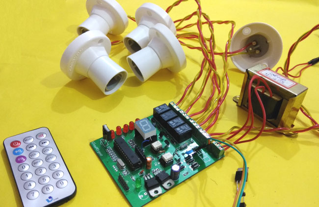
    If any match occurs then the controller performs a relative operation by triggering the respective Relay/Triac and the corresponding result is also indicated by on-board LEDs. Here in this project, we have used 4 bulbs (small bulbs) of different colors as lighting loads and another bulb (bigger bulb) is considered to be a fan for demonstration purpose.
    We have selected key 1 to toggle the relay1, 2 to toggle the relay2, 3 to toggle the relay3, 4 to toggle the relay4, and Vol+ to increase fan speed and Vol- to decrease speed of the fan.
    Note: Here we have used 100watt bulb instead of a fan.

    There are many types of IR Remotes available for different devices, but most of them work around 38KHz Frequency. Here in this project, we control home appliances using IR TV remote and for detecting the IR signals, we use a TSOP1738 IR Receiver. This TSOP1738 sensor can sense 38Khz Frequency signal. The working of IR remote and the TSOP1738 is covered in detail in this article: IR Transmitter and Receiver
    Our PIC microcontroller operates at +5V and the Relays operate at +12V, Hence we use a transformer to step down the 220V AC and rectify it using a full bridge rectifier. This rectified DC voltage is then regulated to +12V and +5V by using the regulator ICs 7812 and 7805 respectively.
    To trigger the relay we make use of transistors like BC547 which can act as an electronic switch to turn ON/OFF the relays based on the signal from the PIC microcontroller.Further to control the speed of the fan we are using a TRIAC. TRIAC is a power semiconductor which is capable of controlling the output voltage; this capability is used to control the speed of the fan.
    We have also used a Triac Driver to control the Triac using our PIC microcontroller. This driver is used to give a firing angle pulse to Triac, so that the output power can be controlled. Here we have used 6 level of speed control. When the level is 0 then the fan will be off. When level will be 1 then speed will be 1/5th of full speed. When level will be 2 then speed will be 2/5th of full speed and respectively for others. The current level of the speed can be monitored using the on-board 7-segment display.

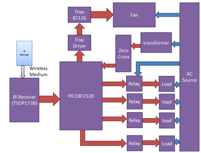
    The block diagram of the project is shown below.
    Working Block Diagram of IR Remote Controlled Home Automation using PIC

    Components: 

    The components required to build this project is given below:
    • PIC18f2520 Microcontroller           -1
    • TSOP1738                                       -1
    • IR TV/DVD Remote                      -1
    • Transistor BC547                            -4
    • Relays 12 volt                                 -4
    • Bulb with holder                             -5
    • Connecting wires                            -
    • EasyEda PCB                                 -1                    
    • 16x2 LCD
    • Power supply 12v
    • Terminal connector 2 pin     `           -8
    • Terminal Connector 3 pin                -1
    • Transformer 12-0-12                       -1                                             -
    • Voltage Regulator 7805                  -1
    • Voltage Regulator 7812                  -1
    • Capacitor 1000uf                            -1
    • Capacitor     10uf                             -1
    • Capacitor     0.1uf                            -1
    • Capacitor 0.01uf 400V       `           -1
    • 10k                                                  -5
    • 1k                                                    -5
    • 100ohm                                           -7
    • Common cathode segment -1
    • 1n4007 diode                                  -10
    • BT136 triac                                     -1
    • Male/female header             -
    • LEDs                                               -6
    • Opto-coupler moc3021                   -1
    • Opto-coupler mtc2e or 4n35           -1
    • 20Mhz crystal                                  -1
    • 33pf capacitor                                 -2
    • 5.1v zener diode                              -1
    • 47 ohm 2 watt resistor                     -1
    All these components are commonly used and can be easily purchased. However if you are looking for a best buy online then we would recommend you LCSC.
    LCSC is a great online store to buy your electronics components for all kinds of projects. They feature about 25,000 kinds of components and the best thing is that they sell even small quantity items for small projects and they also have Global Shipping.

    Decoding the IR Remote:
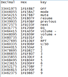
    As said earlier you can use any kind remote for your project. But we have to know what kind of signal is generated for from that particular remote. For every individual key on the remote there will be an equivalent HEX value for that key. Using this HEX value we can distinguish between each key on our microcontroller side. So before we decide to use a remote we should know the HEX value for the keys preset in that particular remote. In this project, we have used a NEC remote. The HEX values for the keys on a NEC remote is given below.
    decimal hex key
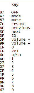
    As you can notice the HEX value has 7 characters out of which only the last two differs, hence we can consider only the last two digits to distinguish between each keys. 
    key1
    Circuit Diagram:
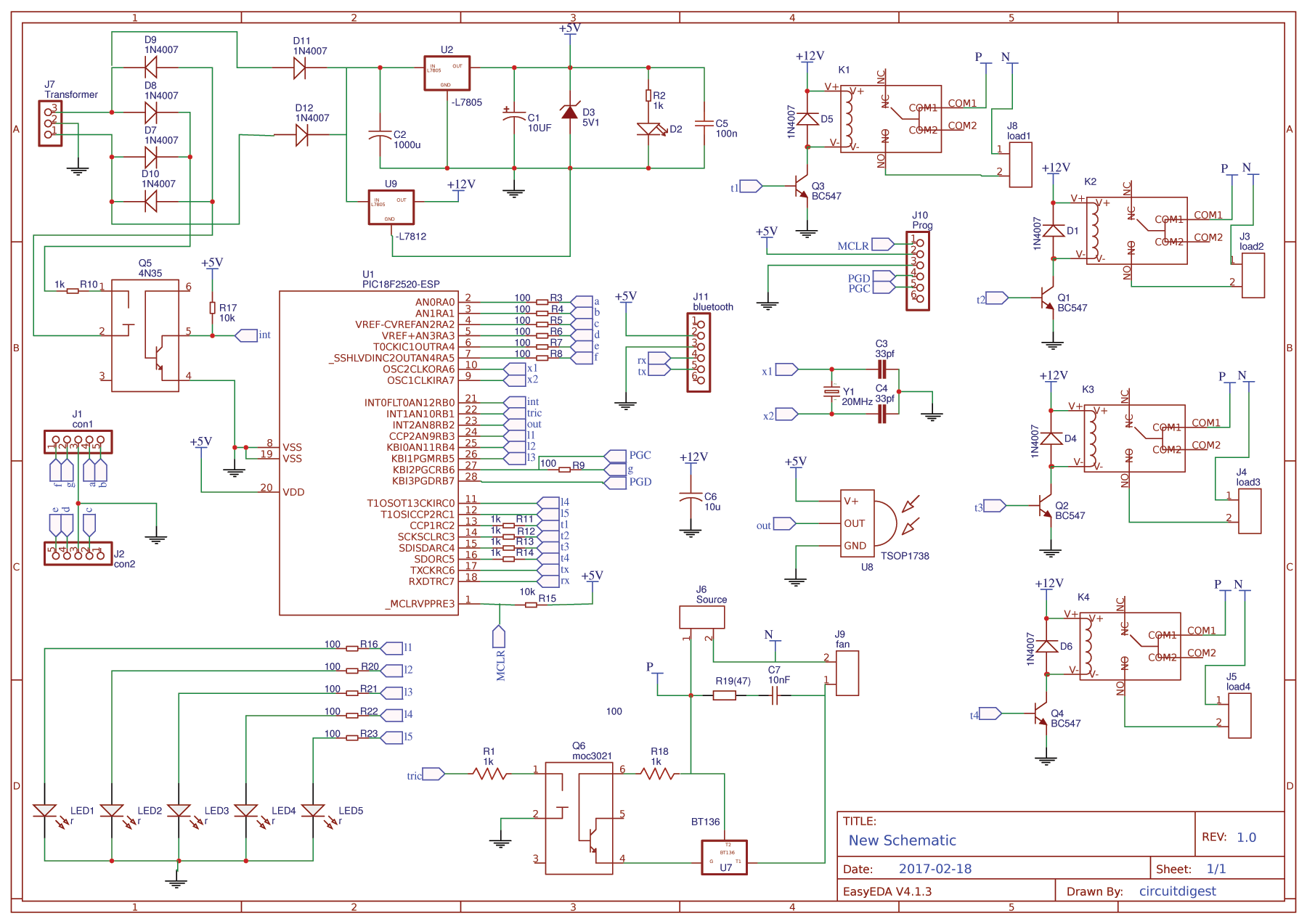
    The schematic for the project is shown below.
     Circuit Diagram for PIC Microcontroller Based Remote Controlled Home Automation
    The above schematic was made easy by using esayEDA schematic editor since they provide the layouts of all components used in this project. It also does not require an installation and can be used online on the go. 
    The pinouts and component values are clearly specified in the schematic above. You can also download the schematic file from here.

    Programming:

    The program for this project is done using MPLABX, the code is also pretty simple and easy to understand. The complete code will be given at the end of this tutorial, further few important chunks of the program are explained below.
    In the beginning of the code, we should include required libraries, define the pins and declare the variables.
    #include <xc.h>
    #include<string.h>
    #include<stdlib.h>
    #include "config.h"
    
    #define tric RB1
    #define ir RB2
    
    #define relay1 RC2
    #define relay2 RC3
    #define relay3 RC4
    #define relay4 RC5
    
    #define rly1LED RB3
    #define rly2LED RB4
    #define rly3LED RB5
    #define rly4LED RC1
    #define fanLED RC0
    
    int flag=0;
    int cmd=0;
    int speed=5;
    unsigned int dat[100];
    int i=0;
    char result[10];
    int j=0;
    
    After that, we have created a simple delay function by using the “for” loop.
    void delay(int time)
    {
        for(int i=0;i<time;i++)
            for(int j=0;j<800;j++);
    }
    After that, we have initialized the timer by using the following function
    void timer()           // 10 -> 1us
    {
       T0PS0=0;
       T0PS1=0;
       T0PS2=0;
       PSA=0;      //Timer Clock Source is from Prescaler
       T0CS=0;     //Prescaler gets clock from FCPU (5MHz)
       T08BIT=0;   //16 BIT MODE
       TMR0IE=1;   //Enable TIMER0 Interrupt
       PEIE=1;     //Enable Peripheral Interrupt
       GIE=1;      //Enable INTs globally
       TMR0ON=1;      //Now start the timer!
    }
    
    Now in the main function, we have give directions to the selected pins and initialize timer and external interrupt int0 to detect zero crossing.
       ADCON1=0b00001111;
       TRISB1=0;
       TRISB2=1;
       TRISB3=0;
       TRISB4=0;
       TRISB5=0;
       TRISC=0x00;
       TRISA=0x00;
       PORTA=0xc0;            
       TRISB6=0;
       RB6=1;
        relay1=0;
        relay2=0;
        relay3=0;
        relay4=0;
        rly1LED=0;
        rly3LED=0;
        rly2LED=0;
        rly4LED=0;
        fanLED=0;
            i=0;
        ir=0;
        tric=0;
        timer();
        INTEDG0 = 0; // Interrupt on falling edge
        INT0IE = 1; // Enable the INT0 external interrupt (RB0)
        INT0IF = 0; // Clears INT0 External Interrupt Flag bit
        PEIE=1;     //Enable Peripheral Interrupt
        GIE=1;      //Enable INTs globally
    Now, here we are not using any interrupt or capture and compare mode to detect IR signal. Here we have just used a digital pin to read data just like we read a push button. Whenever signal goes high or low we just put debouncing method and run the timer. Whenever pin changes its state to another then time values will be saved in an array.
    IR remote send logic 0 as 562.5us and logic 1 as 2250us. Whenever timer reads around 562.5us then we assume it 0 and when timer reads around 2250us then we assume it as 1. Then we convert it in hex.
    The incoming signal from remote contains 34 bits. We store all the bytes in the array and then decode the last byte to use.
          while(ir == 1);
           INT0IE = 0;
           while(ir == 0);
           TMR0=0;
           while(ir == 1);
           i++;
           dat[i]=TMR0;
    
           if(dat[1] > 5000 && dat[1]<12000)
           {
           }
           else
           {
               i=0;
               INT0IE = 1;
           }
    
           if(i>=33)
           {
            GIE=0;
            delay(50);
            cmd=0;
            for(j=26;j<34;j++)
            {
                if(dat[j]>1000 && dat[j]<2000)
                    cmd<<=1;
    
                else if(dat[j]>3500 && dat[j]<4500)
                {
                    cmd|=0x01;
                    cmd<<=1;
                }
            }
            cmd>>=1;
    The above piece of code receives and decodes the IR signal using timer interrupts and stores the corresponding HEX value in the variable cmd. Now we can compare this HEX value (cmd variable) with our predefined HEX values and toggle the relay as shown below
    if(cmd == 0xAF)
             {
                 relay1=~relay1;
                 rly1LED=~rly1LED;
             }
    
             else if(cmd == 0x27)
             {
                 relay2=~relay2;
                 rly2LED=~rly2LED;
             }
            
             else if(cmd == 0x07)
             {
                 relay3=~relay3;
                 rly3LED=~rly3LED;
             }
             else if(cmd == 0xCF)
             {
                 relay4=~relay4;
                 rly4LED=~rly4LED;
             }
             else if(cmd == 0x5f)
             {
                 speed++;
                 if(speed>5)
                 {
                     speed=5;
                 }
             }
    
             else if(cmd == 0x9f)
             {
                 speed--;
                 if(speed<=0)
                 {
                     speed=0;
                 }
             }
    
    Now to know at which our fan is currently operating, we should use a 7-segment display. The following lines are used to instruct the pins of the 7-segment display.
    if(speed == 5)        // turned off  5x2= 10ms triger    //speed 0
            {
                PORTA=0xC0;           // display 0
                RB6=1;
                fanLED=0;            
            }      
    
            else if(speed == 4 )    //  8 ms trigger    //speed 1
            {
                PORTA=0xfc;        // displaying 1
                RB6=1;
                fanLED=1;
            }
           
            else if(speed == 3)   //   6 ms trigger       // speed 2
            {
                PORTA=0xE4;       // displaying 2                   
                RB6=0;
                fanLED=1;
            }
           
            else if(speed == 2)   // 4ms trigger  // speed 3
            {
                PORTA=0xF0;       // displaying 3
                RB6=0;
                fanLED=1;
            }
           
            else if(speed == 1)    // 2ms trigger  // speed 4
            {
                PORTA=0xD9;          // displaying 4
                RB6=0;
                fanLED=1;
            }
        
            else if(speed == 0)        // 0ms trigger  // speed 5  full power
            {
               PORTA=0xD2;            // displaying 5
               RB6=0;
               fanLED=1;
            }
    
    The below function is for external interrupt and time overflow. This function is responsible for detecting zero crossing and driving the Triac.
    void interrupt isr()
    {
        if(INT0IF)
        {
            delay(speed);
            tric=1;
            for(int t=0;t<100;t++);
            tric=0;
            INT0IF=0;
        }
      
       if(TMR0IF)  //Check if it is TMR0 Overflow ISR  
       {
          TMR0IF=0;
       }
    }
    
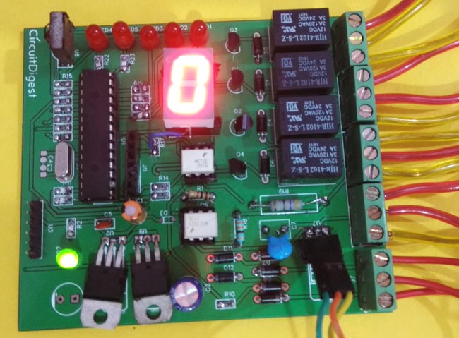
    The final PCB for this IR remote controlled home automation looks as shown below:
    Final PCB for PIC based remote controlled home automation project


    Circuit and PCB Design using EasyEDA:

    To design this  Remote control home automation we have used EasyEDA which is a free online EDA tool for creating circuits and PCBs in a seamless manner. We have previously ordered few PCBs from EasyEDA and still using their services as we found the whole process, from drawing the circuits to ordering the PCBs, more convenient and efficient in comparison of other PCB fabricators. EasyEDA offers circuit drawing, simulation, PCB design for free and also offers high quality but low price Customized PCB service. Check here for the complete tutorial on How to use Easy EDA for making Schematics, PCB layouts, Simulating the Circuits etc.
    EasyEDA is improving day by day; they have added many new features and improved the overall user experience, which makes EasyEDA easier and usable for designing circuits. They are soon going to launch its Desktop version, which can be downloaded and installed on your computer for offline use.
    In EasyEDA, you can make your circuit and PCB designs public so that other users can copy or edit them and can take benefit from there, we have also made our whole Circuit and PCB layouts public for this Remote control Home automation.
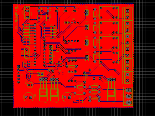
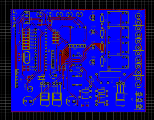
    Below is the Snapshot of Top layer of PCB layout from EasyEDA, you can view any Layer (Top, Bottom, Topsilk, bottomsilk etc) of the PCB by selecting the layer form the ‘Layers’ Window. 
    PCB Design for PIC based IR Remote Controlled Home Automation
    IR Remote Home Automation PCB Design


    Calculating and Ordering PCB Samples online:

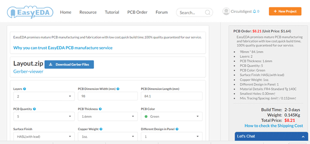
    After completing the design of PCB, you can click the icon of Fabrication output, which will take you on the PCB order page. Here you can view your PCB in Gerber Viewer or download Gerber files of your PCB and send them to any manufacturer, it’s also a lot easier (and cheaper) to order it directly in EasyEDA. Here you can select the number of PCBs you want to order, how many copper layers you need, the PCB thickness, copper weight, and even the PCB color. After you have selected all of the options, click “Save to Cart” and complete your order, then you will receive your PCBs within few days.
    Ordering PCB on EasyEDA
    You can directly order this PCB or download the Gerber file using this link.
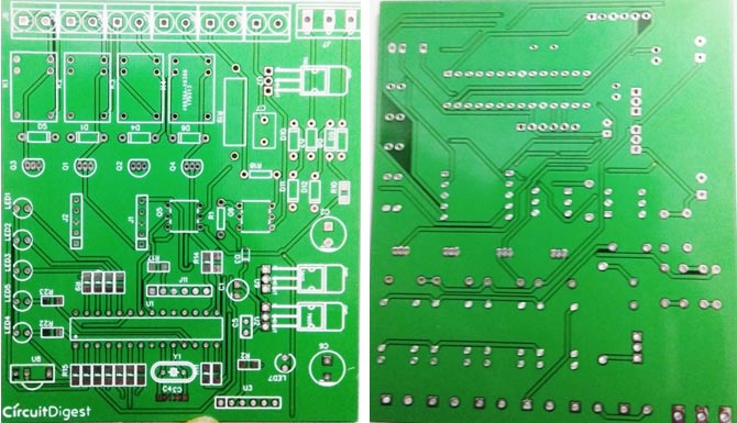
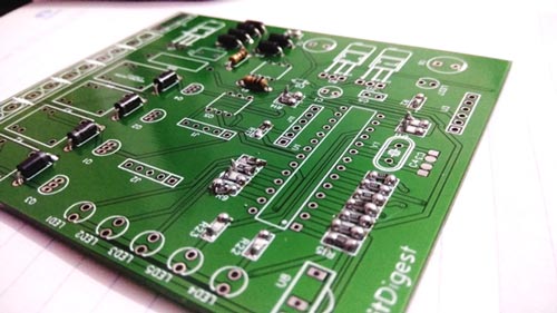
    After few days of ordering PCB’s we got the PCBs. The boards that we received are shown below.
    PCB boards for IR remote controlled home automation project
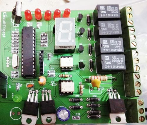
    Once we received the PCBs I mounted all the required components over the PCB, and finally we have our IR Remote Controlled Home Automation ready, check this circuit working in demonstration video at the end of the article.
    PIC home automation PCB after soldering components
    PIC based home automation PCb
    Code

    #include <xc.h>
    #include<string.h>
    #include<stdlib.h>
    #include "config.h"
    #define tric RB1
    #define ir RB2
    #define relay1 RC2
    #define relay2 RC3
    #define relay3 RC4
    #define relay4 RC5
    #define rly1LED RB3
    #define rly2LED RB4
    #define rly3LED RB5
    #define rly4LED RC1
    #define fanLED RC0
    int flag=0;
    int cmd=0;
    int speed=5;
    unsigned int dat[100];
    int i=0;
    char result[10];
    int j=0;
       
    void delay(int time)
    {
        for(int i=0;i<time;i++)
            for(int j=0;j<800;j++);
    }
    void timer()           // 10 -> 1us
    {
       T0PS0=0; 
       T0PS1=0;
       T0PS2=0;
       PSA=0;      //Timer Clock Source is from Prescaler
       T0CS=0;     //Prescaler gets clock from FCPU (5MHz)
       T08BIT=0;   //16 BIT MODE
       TMR0IE=1;   //Enable TIMER0 Interrupt
       PEIE=1;     //Enable Peripheral Interrupt
       GIE=1;      //Enable INTs globally
       TMR0ON=1;      //Now start the timer!
    }
    void main(void) 
    {
       ADCON1=0b00001111;
       TRISB1=0;
       TRISB2=1;
       TRISB3=0;
       TRISB4=0;
       TRISB5=0;
       TRISC=0x00;
       TRISA=0x00;
       PORTA=0xc0;             
       TRISB6=0;
       RB6=1;
        relay1=0;
        relay2=0;
        relay3=0;
        relay4=0;
        rly1LED=0;
        rly3LED=0;
        rly2LED=0;
        rly4LED=0;
        fanLED=0;
            i=0;
        ir=0;
        tric=0;
        timer();
        INTEDG0 = 0; // Interrupt on falling edge
        INT0IE = 1; // Enable the INT0 external interrupt (RB0) 
        INT0IF = 0; // Clears INT0 External Interrupt Flag bit
        PEIE=1;     //Enable Peripheral Interrupt
        GIE=1;      //Enable INTs globally
       while(1)
       {   
           while(ir == 1);
           INT0IE = 0;
           while(ir == 0);
           TMR0=0;
           while(ir == 1);
           i++;
           dat[i]=TMR0;
           
           if(dat[1] > 5000 && dat[1]<12000)
           {
           }
           else
           {
               i=0;
               INT0IE = 1;
           }
           if(i>=33)
           {
            GIE=0;
            delay(50);
            cmd=0;
            for(j=26;j<34;j++)
            {
                if(dat[j]>1000 && dat[j]<2000)
                    cmd<<=1;
                else if(dat[j]>3500 && dat[j]<4500)
                {
                    cmd|=0x01;
                    cmd<<=1;
                }
            }
            cmd>>=1;
             
             if(cmd == 0xAF)
             {
                 relay1=~relay1;
                 rly1LED=~rly1LED;
             }
             
             else if(cmd == 0x27)
             {
                 relay2=~relay2;
                 rly2LED=~rly2LED;
             }
             
             else if(cmd == 0x07)
             {
                 relay3=~relay3;
                 rly3LED=~rly3LED;
             }
             
             else if(cmd == 0xCF)
             {
                 relay4=~relay4;
                 rly4LED=~rly4LED;
             }
             
             else if(cmd == 0x5f)
             {
                 speed++;
                 if(speed>5)
                 {
                     speed=5; 
                 }
             }
             
             else if(cmd == 0x9f)
             {
                 speed--;
                 if(speed<=0)
                 {
                     speed=0; 
                 }
             }
             
            if(speed == 5)        // turned off  5x2= 10ms triger    //speed 0
            {
                PORTA=0xC0;           // display 0
                RB6=1;
                fanLED=0;             
            }
            
            else if(speed == 4 )    //  8 ms trigger    //speed 1
            { 
                PORTA=0xfc;        // displaying 1
                RB6=1;
                fanLED=1;
            }
            
            else if(speed == 3)   //   6 ms trigger     // speed 2
            {
                PORTA=0xE4;       // displaying 2                    
                RB6=0;
                fanLED=1;
            }
            
            else if(speed == 2)   // 4ms trigger  // speed 3
            {
                PORTA=0xF0;       // displaying 3
                RB6=0;
                fanLED=1;
            }
            
            else if(speed == 1)    // 2ms trigger  // speed 4
            {
                PORTA=0xD9;          // displaying 4
                RB6=0;
                fanLED=1;
            }
            
            else if(speed == 0)        // 0ms trigger  // speed 5  full power
            {
               PORTA=0xD2;            // displaying 5
               RB6=0;
               fanLED=1;
            }
            
            else
            {
                RB6=1;
                PORTA=0xff;         // display off
                fanLED=0;
            }
            
            i=0;
            INT0IE = 1;
            GIE=1;
           }
    }
    }
    void interrupt isr()
    {
        if(INT0IF)
        {
            delay(speed);
            tric=1;
            for(int t=0;t<100;t++);
            tric=0;
            INT0IF=0;
        }
        
       if(TMR0IF)  //Check if it is TMR0 Overflow ISR   
       {
          TMR0IF=0;
       }
        
    }